
Movable part of circuit breaker for gas-insulated switchgear

a technology of circuit breakers and switchgear, which is applied in the direction of switchgear arrangements, high-tension/heavy-dress switches, contacts, etc., can solve the problems of inaccurate and firmly fixed components of movable parts, increase in assembly process man-hours, and increase in the number of components, so as to reduce the diameter of movable parts and reduce the number of components. , the effect of miniaturizing the movable parts

Active Publication Date: 2021-07-08
HYOSUNG HEAVY IND CORP
View PDF0 Cites 0 Cited by
  • Summary
  • Abstract
  • Description
  • Claims
  • Application Information

AI Technical Summary

Benefits of technology

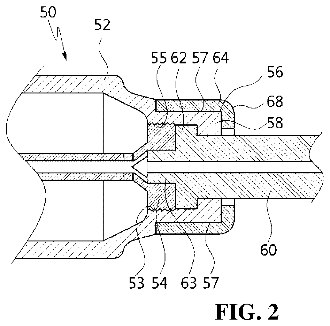
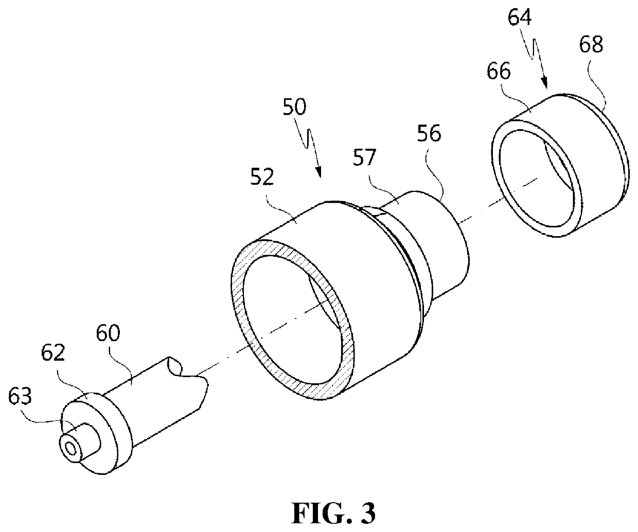
The present invention is about a new design for a circuit breaker used in gas-insulated switchgear. The design uses a press-fitted structure instead of multiple bolts, reducing the number of components. The contact part of the main contact is in close contact with the puffer cylinder's hook part, allowing for longer sections of energy contact. This also reduces the size of the movable part and increases the efficiency of the circuit breaker.

Problems solved by technology

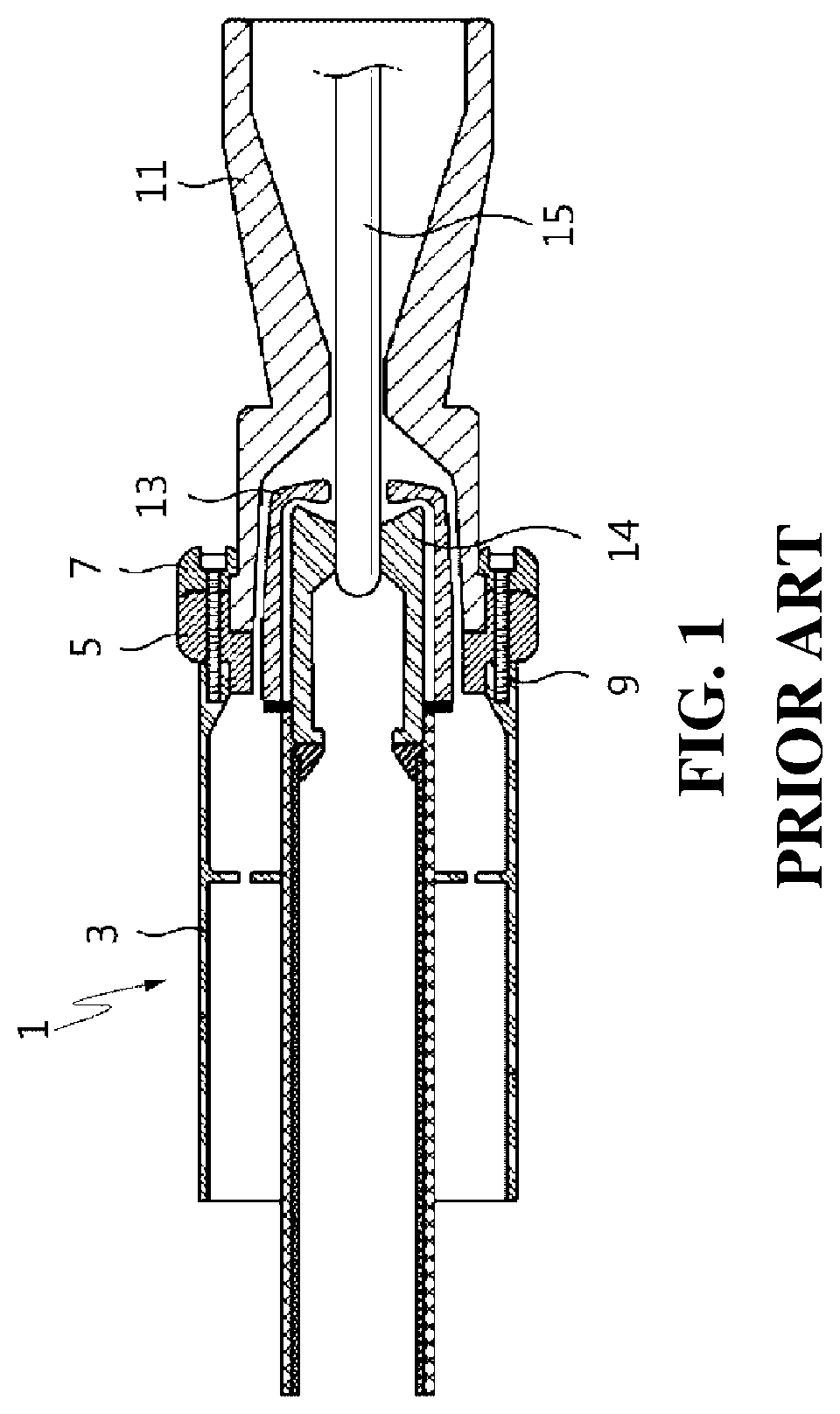
However, the movable part of the gas-insulated switchgear according to the related art as described above has the following problems.
Therefore, there is a problem in that man-hours in an assembly process increases and the total number of components increases.
In addition, the bolt 9 has a problem in that some components of the movable part 1 are not accurately and firmly fixed because of loosening due to vibration or the like generated during use of the movable part 1.
In addition, there is a problem in that the contact surface for electrical connection, which leads to the main contact 7, the nozzle body 5, and the puffer cylinder 3, is relatively narrow.
Therefore, there is a problem in that the movable part 1 should be increased in size in order to increase the contact area for energization.

Method used


Image

  • Movable part of circuit breaker for gas-insulated switchgear
  • Movable part of circuit breaker for gas-insulated switchgear
  • Movable part of circuit breaker for gas-insulated switchgear

Examples


Embodiment Construction

[0026]Hereinafter, some exemplary embodiments of the present invention are described in detail with reference to the accompanying drawings. In adding reference numerals to the components of each drawing, it should be noted that the same reference numerals are used to refer to the same components as much as possible even if displayed on different drawings. Further, in the following description, if it is decided that the detailed description of a known function or configuration related to the invention makes the subject matter of the invention unclear, the detailed description is omitted.

[0027]Further, when describing the components of the present invention, terms such as first, second, A, B, (a) or (b) may be used. Since these terms are provided merely for the purpose of distinguishing the components from each other, they do not limit the nature, sequence, or order of the components. If a component is described as being “connected”, “coupled”, or “linked” to another component, that c...


PUM


Abstract

A movable part of a circuit breaker for a gas-insulated switchgear is proposed. The movable part includes a puffer cylinder, a nozzle, a main contact, etc. An outer rib at the rear end of the nozzle is hooked to a hook rib at the front end of the hook part of the puffer cylinder. A chamber guide is provided inside the puffer cylinder so that the nozzle is immobilized. The main contact is mounted on the outer surface of the front end of the hook part. In the present invention, the number of components constituting the movable part of the circuit breaker is reduced, and the number of bolting points is reduced, thereby greatly reducing man-hours in an assembly work and preventing a main contact separation from occurring due to bolt loosening.

Description

TECHNICAL FIELD[0001]The present invention relates to a gas-insulated switchgear and, more particularly, to a movable part of a circuit breaker for a gas-insulated switchgear that moves for an on-off operation in the circuit breaker.BACKGROUND ART[0002]A gas-insulated switchgear is an electrical facility that improves reliability by storing conductors and various protective devices with insulating gas (SF6), which has excellent insulating and extinguishing performance, in an enclosure which is a sealed metal container. The gas-insulated switchgear includes a circuit breaker, a line disconnector, and a ground switch.[0003]Meanwhile, the circuit breaker of the gas-insulated switchgear generally has a fixed part and a movable part, and connects or disconnects a line while the movable part moves. Such a movable part is generally composed of a puffer cylinder, a nozzle, and a main contact.[0004]For reference, FIG. 1 schematically shows a configuration of a circuit breaker of a general ga...

Claims


Application Information

Patent Timeline
Patent Type & Authority Applications(United States)
IPC IPC(8): H01H33/70
CPCH01H33/7061H01H33/7038H01H33/7084H02B13/035H01H33/7023H01H1/385H01H33/42
Inventor LEE, SANG WOOPARK, SU HYUN
Owner HYOSUNG HEAVY IND CORP
Learn More