Support structure for vehicle component

a technology for supporting structures and vehicle components, applied in the direction of superstructure subunits, propulsion parts, vehicle components, etc., can solve the problems of reducing the impact absorption capacity of vehicle components, preventing a given deformation of the side frame in an offset collision, and affecting the planned deformation of the side frame, so as to reduce the vibration of the vehicle componen

Active Publication Date: 2021-08-05
MAZDA MOTOR CORP
View PDF0 Cites 5 Cited by
  • Summary
  • Abstract
  • Description
  • Claims
  • Application Information

AI Technical Summary

Benefits of technology

[0006]Therefore, one purpose of the present disclosure is to reduce vibration of a vehicle component while securing an impact absorption capability by a skeleton member in an offset collision.
[0010]According to this structure, a contact area of the vehicle component of which the longitudinal direction is oriented toward the vehicle up-and-down direction and is inclined in the vehicle front-and-rear direction, is made to be small as if it point-contacts the suspension tower housing, and the force for deforming the support member can act smoothly.
[0012]According to this structure, since the vehicle component is supported such that the longitudinal direction of the vehicle component is oriented in and parallel to the extending direction of the side member, the vehicle component is supported at a location closer to the side member and with the small influence by the vehicle vibration. Moreover, since the vehicle component is inclined so that the lower end in the longitudinal direction is located rearward of the upper end, the space can be secured between the vehicle component and the suspension tower housing. Therefore, the distance for the vehicle component passing by the suspension tower housing can be fully acquired, and the deformation of the side frame and the displacement of the vehicle component can be ensured.
[0014]According to this structure, when the load is inputted to the free-end-side part via the vehicle component, the load is concentrated on the stepped part. That is, the stepped part becomes a deformation part so that the deformation of the support member which deflects the vehicle component inwardly can be performed smoothly.
[0016]According to this structure, since the support member is comprised of the plate member, and the plate surfaces which are surfaces of the plate member with large areas are oriented in the vehicle width direction to which the deformation is intended, the load can be concentrated effectively compared to a case where the support member is comprised of bar members, and the rearward-moving course of the vehicle component can more smoothly be turned inward.

Problems solved by technology

In such a structure, if the vehicle component is fixed above the side frame and forward of the suspension tower housing, it may impede a given deformation of the side frame in an offset collision.
That is, although the vehicle component moves rearward according to the side frame which is shortened in the length by the collision, the vehicle component then hits the suspension tower housing, thereby impeding the planned deformation of the side frame.
In such a case, a desired impact absorption capability cannot be obtained.

Method used


Image

  • Support structure for vehicle component
  • Support structure for vehicle component
  • Support structure for vehicle component

Examples


Embodiment Construction

[0029]Hereinafter, one embodiment for implementing the present disclosure is described with reference to the accompanying drawings.

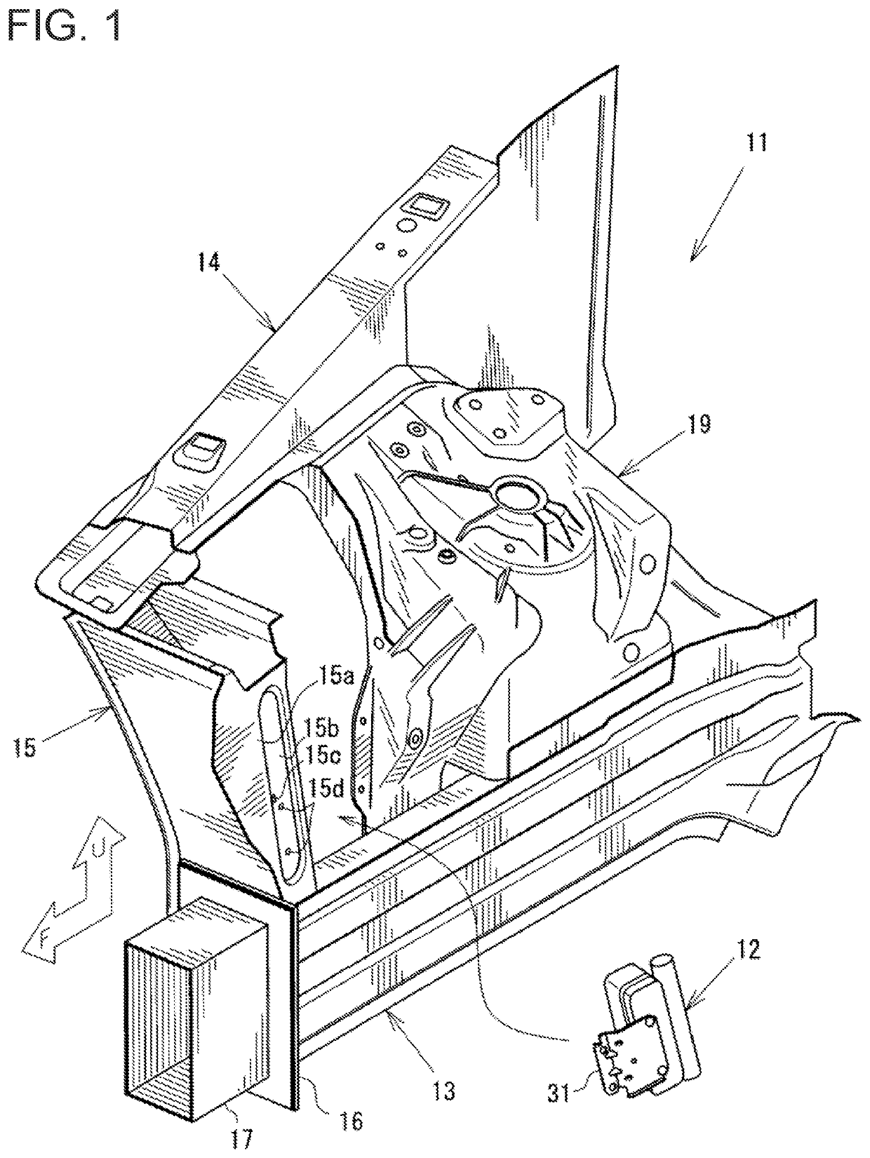
[0030]In a support structure for a vehicle component disposed inside a power-unit chamber where a powertrain unit of a vehicle is disposed, the present disclosure is to reduce vibration of the vehicle component while securing an impact absorption capability by a skeleton member in an offset collision. In this example, a water-cooled condenser which constitutes an air conditioning system is described as the vehicle component.

[0031]FIG. 1 illustrates a perspective view of a vehicle-body frame 11 which constitutes the power-unit chamber, and a water-cooled condenser 12 supported by the vehicle-body frame 11. FIG. 1 illustrates only the right side of the vehicle in the vehicle width direction and as illustrated by a white arrow, the lower left in this drawing is front or forward of the vehicle and the up in this drawing is up or upward of the vehicle. “F” of...


PUM


Abstract

A support structure is provided for a vehicle component disposed inside a power-unit chamber where a powertrain unit of the vehicle is disposed. The support structure includes the power-unit chamber including a side frame extending in a vehicle front-and-rear direction, and a suspension tower housing formed overlapping with a part of the side frame in a plan view seen from above the vehicle. The vehicle component is disposed at a location where the vehicle component overlaps with the side frame in the plan view and forward of the suspension tower housing in the vehicle front-and-rear direction. The vehicle component is supported by one of the side frame, and a support member coupled to an inward side surface of a closed-cross-section member connected to the side frame at a location forward of the suspension tower housing in the vehicle front-and-rear direction.

Description

TECHNICAL FIELD[0001]The present disclosure relates to a support structure for disposing a vehicle component, such as a water-cooled condenser and an electric water pump, in a power-unit chamber of a vehicle where a powertrain unit is disposed.BACKGROUND OF THE DISCLOSURE[0002]JP2019-031188A discloses a vehicle component disposed in a power-unit chamber. According to the structure, the vehicle component is fixed to a side frame extending in a vehicle front-and-rear direction in the power-unit chamber. The fixed position of the vehicle component is forward of a suspension tower housing of the side frame, and on an outward side surface of the side frame in a vehicle width direction. A suspension bracket is used for fixing the vehicle component.[0003]The fixed position of the vehicle component is desirable to be near a skeleton member which constitutes a frame of the vehicle body in consideration of a shake of the vehicle component caused by vibration of the vehicle.[0004]However, some...

Claims


Application Information

Patent Timeline
Patent Type & Authority Applications(United States)
IPC IPC(8): B62D21/02B62D25/08B62D21/11
CPCB62D21/02B62D21/11B62D25/082B60K11/02B62D25/088
Inventor KIRITA, KOHEIYAMAUCHI, SHINJI
Owner MAZDA MOTOR CORP
Why Eureka
Try Eureka