Amphibious Aircraft Taxiing and Docking Systems

a technology for aircraft taxiing and docking, applied in the direction of marine propulsion, steering initiation, vessel construction, etc., can solve the problems of real and hazardous situations, low-speed taxiing maneuvering, and increase the risk of life and property damage, which can cost over three million dollars

Active Publication Date: 2021-08-05
THEY
View PDF0 Cites 8 Cited by
  • Summary
  • Abstract
  • Description
  • Claims
  • Application Information

AI Technical Summary

Benefits of technology

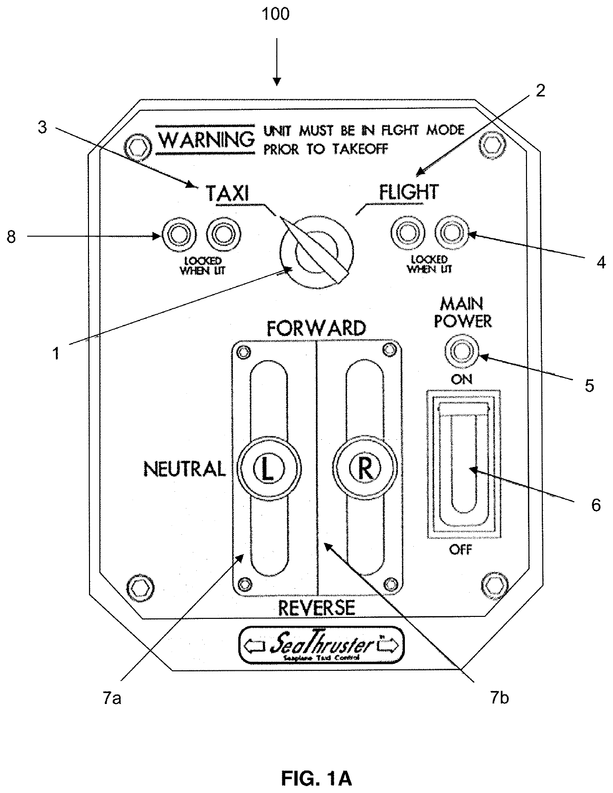
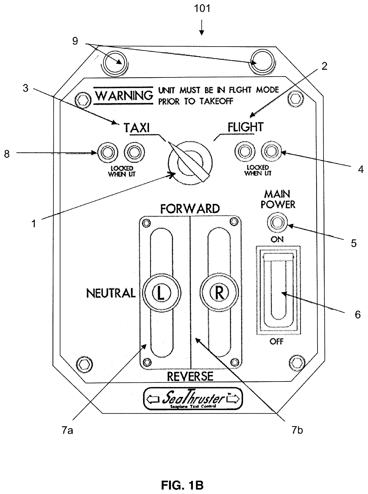
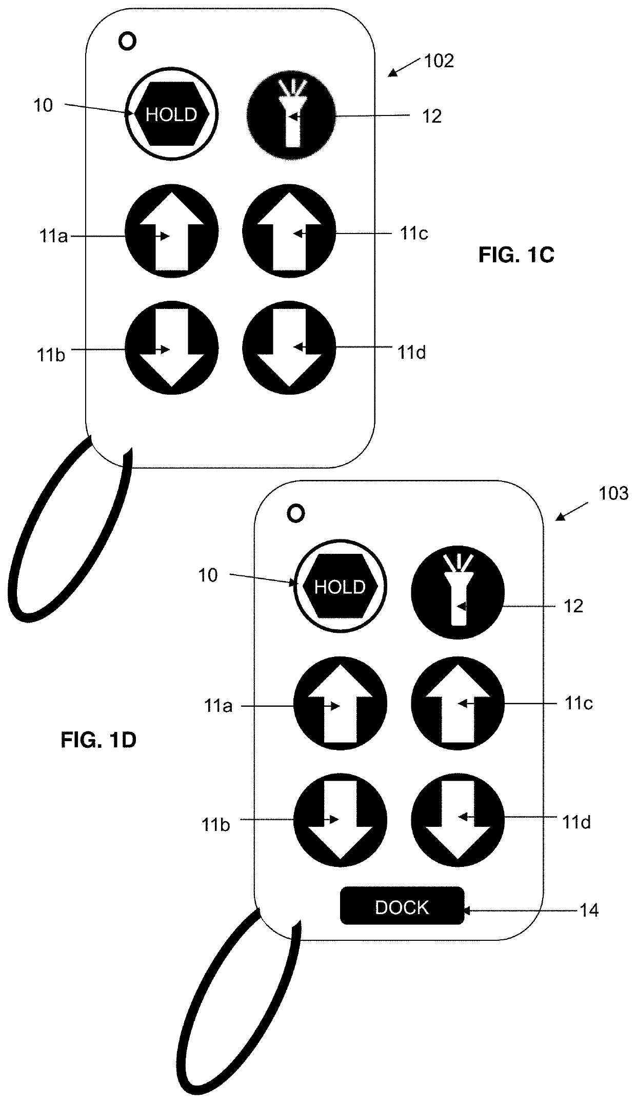
[0006]The present invention is directed to a taxiing system for steering an amphibious aircraft on a body of water. The device comprises a pair of pods, a control console and a power source. Each of the pair of pods has a proximal end and a distal end and each is mounted on a float on the aircraft. Each pod comprises an enclosure formed within at the proximal end and a cradle formed within at the distal end. A thruster is housed within the cradle and is removably deployable during taxiing. A thruster deployment assembly is housed within the enclosure and is in mechanical communication with the thruster. The control console is in operable communication with the thruster deployment assembly and the power source is in electrical communication with the thruster, the thruster deployment assembly and the control console.

Problems solved by technology

However, a basic understanding of fluid dynamics and the interaction of a plane operating in that environment brings to light some very real and hazardous situations that a pilot must acknowledge and overcome.
One of the primary and consistently prevalent problems is low-speed taxi maneuvering.
Such accidents increase the risk to life and property damage that can cost over three million dollars.
At slow speeds, even a draft of wind can send the plane moving in an uncontrolled direction with potentially disastrous results.
Such precise control is complicated by aircraft design, which makes it difficult to apply existing methods uniformly for all aircraft.
Overall, there is a deficiency in the art for optimal maneuvering systems for amphibious aircraft.

Method used


Image

  • Amphibious Aircraft Taxiing and Docking Systems
  • Amphibious Aircraft Taxiing and Docking Systems
  • Amphibious Aircraft Taxiing and Docking Systems

Examples


Embodiment Construction

[0020]For convenience, before further description of the present invention, certain terms employed in the specification, examples and appended claims are collected herein. These definitions should be read in light of the remainder of the disclosure and understood as by a person of skill in the art. Unless defined otherwise, all technical and scientific terms used herein have the same meaning as commonly understood by a person of ordinary skill in the art.

[0021]The articles “a” and “an” when used in conjunction with the term “comprising” in the claims and / or the specification, may refer to “one”, but is also consistent with the meaning of “one or more”, “at least one”, and “one or more than one”. Some embodiments of the invention may consist of or consist essentially of one or more elements, components, method steps, and / or methods of the invention. It is contemplated that any composition, component or method described herein can be implemented with respect to any other composition, ...


PUM


Abstract

Provided herein is a taxiing system for for steering an amphibious aircraft on a body of water. The system has a pair of thrusters that are deployed after landing on the water to taxi the amphibious the aircraft prior to docking and to unloading and are retractable to taxi the amphibious aircraft prior to take-off. Also provided is a docking device to dock the amphibious aircraft to a mooring buoy. In addition provided herein is a system for maneuvering an amphibious aircraft during taxiing and docking on water that integrates the taxiing system with the docking device.

Description

BACKGROUND OF THE INVENTIONField of the Invention[0001]The present invention is in the field of aircraft control systems. More specifically, the present invention is directed to systems and devices for amphibious aircraft taxiing and docking control.Description of the Related Art[0002]Amphibious aircrafts have a distinct advantage over land-based planes in availability of landing sites and their ability to operate from remote locations.[0003]However, a basic understanding of fluid dynamics and the interaction of a plane operating in that environment brings to light some very real and hazardous situations that a pilot must acknowledge and overcome. One of the primary and consistently prevalent problems is low-speed taxi maneuvering. A survey (F.A.A. Accident Survey 1992 Doc#1825.23) concluded that over 87% of amphibious accidents occurred while taxiing in close proximity to obstructions such as docks, fueling stations, other planes. Such accidents increase the risk to life and proper...

Claims


Application Information

Patent Timeline
Patent Type & Authority Applications(United States)
IPC IPC(8): B63B35/68B64C35/00B63H21/17B64F1/12B63H25/02B63H23/02
CPCB63B35/68B64C35/008B63H21/17B63H2025/028B64C35/001B63H25/02B63H23/02B64F1/12B63H2025/465B64C35/005
Inventor THEY
Owner THEY
Why Eureka
Try Eureka