Coaxial connector with partition

a technology of coaxial connector and partition, which is applied in the direction of coupling device connection, two-part coupling device, electrical apparatus, etc., can solve the problems of crosstalk failure, deterioration of transmission characteristics of radio frequency signal transmitted through the first signal contact and radio frequency signal transmitted through the second signal contact, etc., to reduce the number of components, simplify the structure, and suppress the effect of deterioration of transmission characteristics

Active Publication Date: 2021-08-05
AIHATA
View PDF3 Cites 3 Cited by
  • Summary
  • Abstract
  • Description
  • Claims
  • Application Information

AI Technical Summary

Benefits of technology

[0013]According to the coaxial connector device of the present disclosure, the first signal contact member and the second signal contact member disposed inside the annular fitting portion of the ground contact member are disposed close to each other with a small gap. Accordingly, an area occupied by the coaxial connector device in a parts mount surface of a circuit board to which a mate coaxial connector device corresponding to the coaxial connector device according to the present disclosure is attached may be reduced. Further, since the flat partition provided with the ground potential is disposed in the small gap between the first signal contact member and the second signal contact member, the first signal contact member and the second signal contact member are electromagnetically shielded from each other by the flat partition provided with the ground potential. Accordingly, the radio frequency signal transmitted through the first signal contact membe

Problems solved by technology

As a result, transmission characteristics of the radio frequency signal transmitted through the first signal contact and the radio frequency signal transmitted through the second signal contact may be deteriorated.
That is, for example, there is a possibility of causing a crosstalk failure in which the radio frequency signal tran

Method used


Image

  • Coaxial connector with partition
  • Coaxial connector with partition
  • Coaxial connector with partition

Examples


Embodiment Construction

[0031]Hereinafter, with reference to the drawings, the same elements or similar elements having the same function are denoted by the same reference numerals, and redundant description will be omitted.

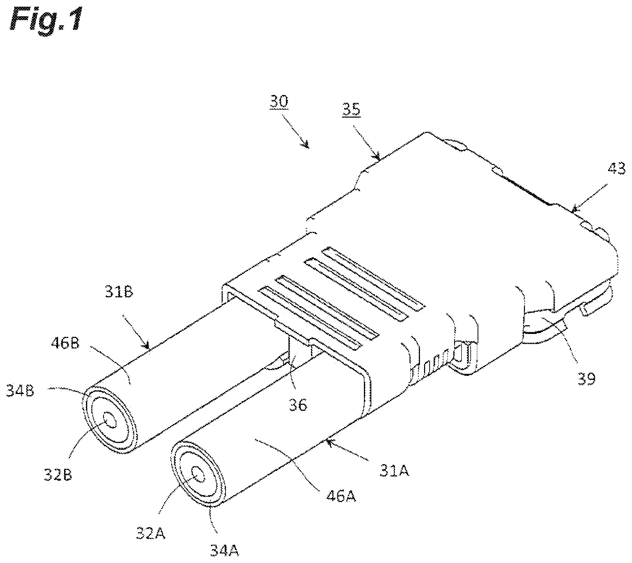
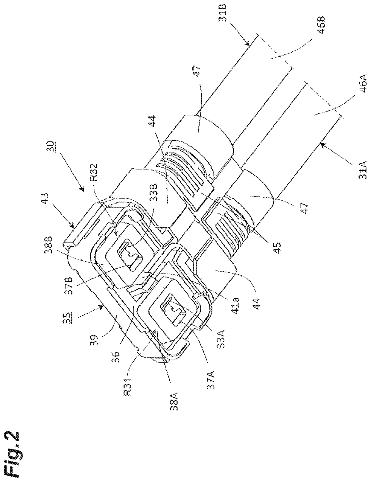
[0032]FIGS. 1 and 2 show a coaxial connector device 30, which is an example of a coaxial connector device, with respective portions of a first coaxial cable 31A (a first cable) and a second coaxial cable 31B (a second cable) connected thereto.

[0033]As shown in FIGS. 1 and 2, the coaxial connector device 30 is used as a cable side coaxial connector device that is fitted and connected to a mate coaxial connector device which is a board side coaxial connector device attached to a parts mount surface of a circuit board in a state in which first and second coaxial cables 31A and 31B are connected to the coaxial connector device 30. For example, the coaxial connector device 30 is a connector for connecting the first and second coaxial cables 31A and 31B to a mate connector having a mate first...


PUM


Abstract

A coaxial connector device includes a first signal contact member joined to a central conductor of a first coaxial cable, a second signal contact member joined to a central conductor of a second coaxial cable, a ground contact member has an annular fitting portion arranged around the first and second signal contact members and is joined to the outer conductors of the respective first and second coaxial cables, and a flat partition provided with a ground potential and located between the first signal contact member and the second signal contact member.

Description

CROSS-REFERENCE TO RELATED APPLICATIONS[0001]This application is a continuation application of PCT Application No. PCT / JP2019 / 041572, filed on Oct. 23, 2019, which claims the benefit of priority from Japanese Patent Application No. 2018-201508, filed on Oct. 26, 2018, the entire contents of which are incorporated herein by reference.BACKGROUND1. Field[0002]The present disclosure relates to a coaxial connector device in which a plurality of coaxial cables are connected. The coaxial connector device to which the plurality of coaxial cables are connected is fitted and connected to a mate coaxial connector device attached to the circuit board to electrically connect the plurality of coaxial cables to the circuit board.2. Description of the Related Art[0003]For transmission of a radio frequency signal between a plurality of electric components, electric devices, electronic apparatuses, or the like, a coaxial cable is used in many cases, in which a central conductor and an outer conductor...

Claims


Application Information

Patent Timeline
IPC IPC(8): H01R13/6585H01R24/50H01R9/05H01R12/52
CPCH01R13/6585H01R12/52H01R9/05H01R24/50H01R13/6589H01R12/57
Inventor NAKAGAWA, YUTA
Owner AIHATA
Why Eureka
Try Eureka