Air vent device for vehicle

Active Publication Date: 2021-08-26
HYUNDAI MOTOR CO LTD +2
View PDF0 Cites 0 Cited by
  • Summary
  • Abstract
  • Description
  • Claims
  • Application Information

AI Technical Summary

Benefits of technology

The present invention is an air vent device for vehicles that allows for control of the air direction through the vehicle. It includes an upper rear wing and a lower rear wing mounted within an air duct that can move linearly along the front-rear direction. The front ends of the upper and lower rear wings are also rotatably mounted with upper and lower air guide wings, which can be rotated upward or downward to control the air direction. This design allows for precise control of the air direction in the vehicle, improving its comfort and performance.

Problems solved by technology

Although an existing air vent may be formed of a structure with a large vertical height while the number of horizontal wings and vertical wings thereof is at least 5 and 6, respectively, thereby easily controlling the direction of the air discharged into the interior toward the passenger's body, there is a drawback in that the size of the air vent is inevitably increased, thereby affecting the package problem with the surrounding components and the design constraint conditions.
Furthermore, as the driver needs to control the vertical wind direction by directly and vertically bending back a knob, which is attached to a horizontal wing among components of the existing air vent, the driver may not pay attention to the front temporarily while driving, thereby also causing a problem in running safety.
In addition, since the existing air vent has a structure in which numerous horizontal wings and vertical wings are inevitably exposed in appearance, the air vent occupies a wide mounting space in the center fascia panel or the crash pad, thereby eventually degrading the degree of freedom of the design of a cluster, an Audio, Video, Navigation (AVN) device, and the like, which are disposed around the air vent.
However, the slim-type air vent has a drawback in that it is not possible to conveniently control the vertical direction of the air discharged into the interior.
For example, as the slim-type air vent is mounted to the exit position of the air duct in a structure in which only a single horizontal wing is exposed to the outside, it is inconvenient for the driver to operate by directly holding the single horizontal wing by hand in order to control the vertical wind direction.
Thirdly, only the pair of rear wings and the pair of air guide wings may be required as compared to numerous wind direction control wings configuring the existing general air vent, thereby reducing the number of components and saving the manufacturing costs.

Method used


Image

  • Air vent device for vehicle
  • Air vent device for vehicle
  • Air vent device for vehicle

Examples


Embodiment Construction

[0039]Hereinafter, preferred embodiments of the present disclosure will be described in detail with reference to the accompanying drawings.

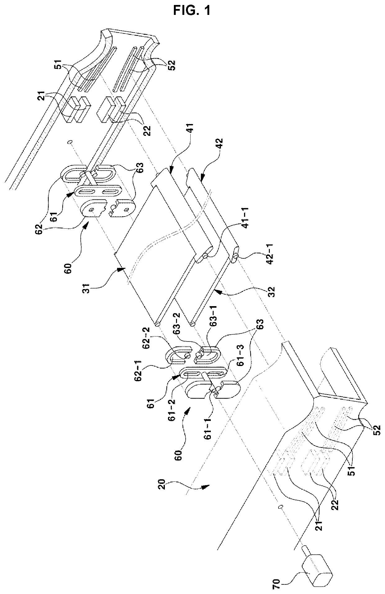
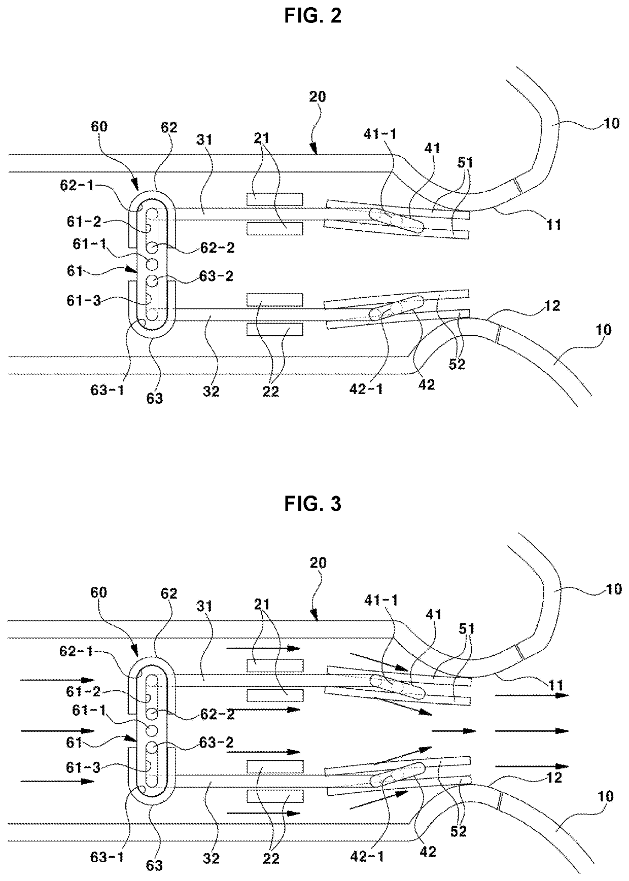
[0040]FIG. 1 is an exploded perspective diagram illustrating an air vent device for a vehicle according to the present disclosure, FIG. 2 is a side cross-sectional diagram illustrating the assembled state of the air vent device for the vehicle according to the present disclosure, and reference numeral 10 in FIG. 2 denotes a garnish.

[0041]The garnish 10 refers to a kind of decoration which is mounted to the position of the air discharge port of the center fascia panel or is mounted at the position of the air discharge port of the crash pad, and an air duct 20, which is the passage of air from an air conditioner toward the interior, is arranged on the rear portion of the garnish 10.

[0042]Preferably, the upper end portion of the outlet of the air duct 20 and the garnish 10 being in close contact therewith are formed of a downward convex curved surfa...


PUM


Abstract

The present disclosure provides an air vent device for a vehicle, which may be mounted with an upper rear wing and a lower rear wing within an air duct to be linearly movable along the front-rear direction, and be rotatably mounted with an upper air guide wing and a lower air guide wing at the front end portions of the upper rear wing and the lower rear wing, thereby controlling the wind direction of the air downward while the upper air guide wing rotates downward when the upper rear wing moves forward, or controlling the wind direction of the air upward while the lower air guide wing rotates upward when the lower rear wing moves forward.

Description

CROSS REFERENCE TO RELATED APPLICATIONS[0001]This application claims under 35 U.S.C. § 119(a) the benefit of priority to Korean Patent Application No. 10-2020-0023365 filed on Feb. 26, 2020, the entire contents of which are incorporated herein by reference.BACKGROUND(a) Technical Field[0002]The present disclosure relates to an air vent device for a vehicle, and more particularly, to a motor-driven air vent device for a vehicle, which may easily control the vertical wind direction of the air discharged into the interior by using a rear wing which performs linear motion, an air guide wing which conducts rotary motion, or the like.(b) Background Art[0003]Generally, an air vent which discharges air into the interior by an operation of an air conditioner for a vehicle includes a center air vent which is mounted to a center fascia panel between the front surfaces of the driver seat and the passenger seat, side vents which are mounted to crash pads on the front surface sides of the driver ...

Claims


Application Information

Patent Timeline
IPC IPC(8): B60H1/34B60H1/00
CPCB60H1/3428B60H2001/3471B60H1/00671B60H1/00564B60H1/3414B60H1/3421B60H2001/3464
Inventor KIM, JOO HWAKIM, SEUNG CHEOLKIM, WON SIK
Owner HYUNDAI MOTOR CO LTD
Why Eureka
Try Eureka