
Headgear such as a cap

a technology of headgear and caps, applied in the field of headwear, can solve the problems of unattractive snap fastener technology, complex manufacturing process, lack of versatility of caps, etc., and achieve the effects of simple and fast use, good elastic grip, and increased rigidity of assembly

Inactive Publication Date: 2021-09-02
BAPTISTA CHRISTOPHE
View PDF37 Cites 1 Cited by
  • Summary
  • Abstract
  • Description
  • Claims
  • Application Information

AI Technical Summary

Benefits of technology

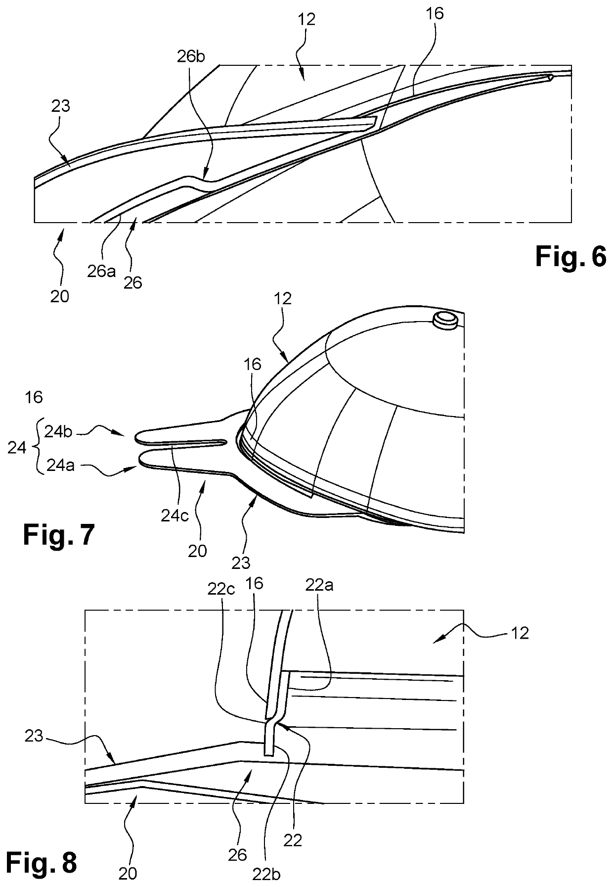
The invention is a new type of headwear that combines a visor and sweatband. The link between the two is made by hooks that can bend and fit tightly around the sweatband attached to the head, creating a rigid assembly. The hooks are positioned in opposite directions, which ensures a snug fit and keeps the visor in place. The sweatband can also have a central portion that stiffens the visor, making it easier to adjust. This design is simpler and faster to use than previous technology.

Problems solved by technology

However, visors are usually fixed so that a wearer has to choose between several pairs of crowns / visors without the combination made by the manufacturer being perfectly suitable for him / her.
It is therefore understandable that these caps lack versatility.
While a cap of this design does indeed allow a visor to be replaced easily, it has the disadvantage of being complex to manufacture, particularly with regard to the perpendicular fastening wall.
Furthermore, the means of fastening used requires that the positioning before joining be very precise, which often requires several attempts, as the scratch straps tend to come together before proper positioning.
However, this snap fastener technology proves to be unattractive since the thickness of the snap fasteners makes it difficult, if not impossible, to conceal them in the thickness of the strips.
Furthermore, the very principle of fastening by means of connecting points at a distance from each other does not allow sufficient tension to be applied to the visor and / or the crown, or else requires very precise positioning and dimensioning of the visor eyelets and the first parts of the crown.
For these reasons, this headwear is not suitable for a demanding wearer.

Method used


Image

  • Headgear such as a cap
  • Headgear such as a cap
  • Headgear such as a cap

Examples


Embodiment Construction

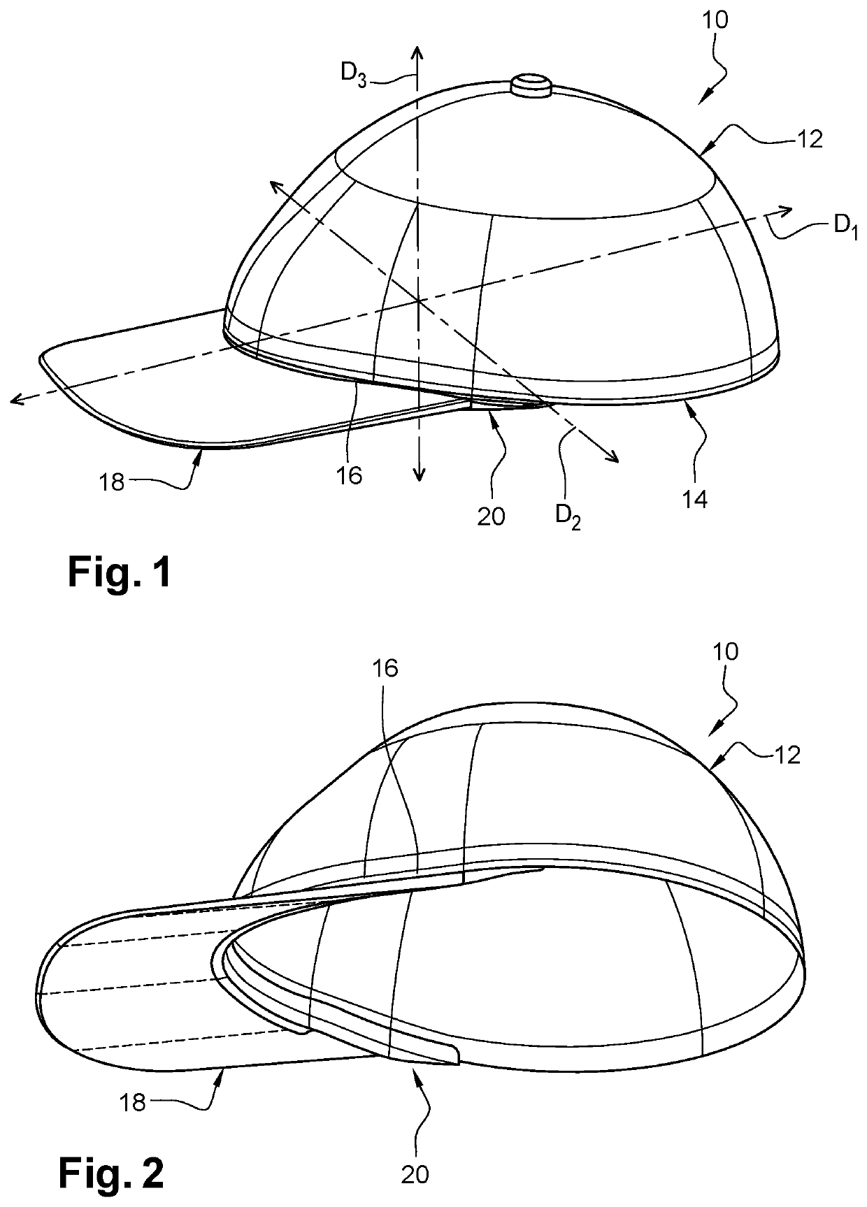
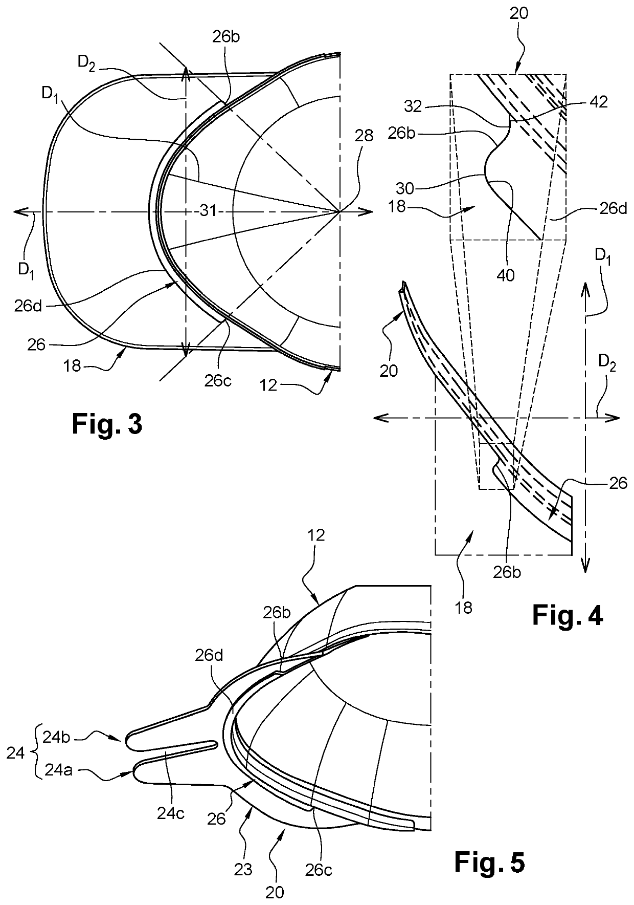
[0032]FIGS. 1 to 3 are schematic views in perspective and in different orientations of a headwear 10 depending on the invention. The headwear here is a cap 10 called American cap since it includes a crown 12 or skullcap in the shape of a half-sphere. This crown 12 comprises a lower free peripheral edge 14 of which a curved part 16 is connected to a visor 18 for eye and / or face protection.

[0033]The different parts of the cap 10 are here exposed in relation to three directions in space, a first direction D1 is a direction perpendicular to the curved part 16 at a midpoint thereof, the second direction D2 is a direction perpendicular to the first direction D1 and a third direction D3 which is also perpendicular to the first direction D1.

[0034]The visor 18 shown here has a substantially straight shape in the first direction D1 and a substantially rounded shape in the second direction D2. However, it is easy to understand that the invention is not limited to this form of visor 18 and that...


PUM


Abstract

The invention concerns a headwear, in particular a cap, including a crown and a visor and a rigid sweatband integral with a curved part of the peripheral edge of the crown (and on which the visor is intended to be assembled, in which the sweatband includes at least a first hook and a second hook angularly spaced and angularly oriented in opposite directions to each other around the curved portion, and able to cooperate by elastic snap-fitting, respectively, with at least a first hook and a second hook of the visor in a direction of elastic assembly and disassembly of the visor on the sweatband.

Description

FIELD OF THE INVENTION[0001]The invention concerns a headwear and in particular a cap, known as an American cap. The invention is not however by any means limited to this type of cap.BACKGROUND OF THE INVENTION[0002]Classically, a headwear and more specifically a cap comprises two parts, a first part is formed by the crown intended to be secured, i.e. assembled, on the head of the wearer and which allows the headwear to be kept on the head. This crown also provides thermal and rain protection. A second part is formed by the visor that protects the wearer from excess light but also protects the face from rain, which is particularly appreciated by persons who wear glasses.[0003]The visor can be of various shapes and sizes to accommodate the different aesthetic wishes of the wearer. However, visors are usually fixed so that a wearer has to choose between several pairs of crowns / visors without the combination made by the manufacturer being perfectly suitable for him / her. It is therefore...

Claims


Application Information

Patent Timeline
Patent Type & Authority Applications(United States)
IPC IPC(8): A42B1/0184
CPCA42B1/0184
Inventor BAPTISTA, CHRISTOPHE
Owner BAPTISTA CHRISTOPHE
Learn More