Picture decoding device, picture decoding method, and picture decoding program

Pending Publication Date: 2021-09-02
JVC KENWOOD CORP A CORP OF JAPAN
View PDF0 Cites 0 Cited by
  • Summary
  • Abstract
  • Description
  • Claims
  • Application Information

AI Technical Summary

Benefits of technology

The present patent aims to improve coding efficiency for picture coding and decoding by using block partitioning. The invention provides a technique for increasing coding efficiency and allows for better performance in video processing.

Problems solved by technology

When a block is not partitioned into blocks of an appropriate size and shape, the coding efficiency will decrease.
In particular, at a frame end, a block containing pixels located beyond a picture boundary has an inappropriate size and shape, and the coding efficiency decreases accordingly.

Method used


Image

  • Picture decoding device, picture decoding method, and picture decoding program
  • Picture decoding device, picture decoding method, and picture decoding program
  • Picture decoding device, picture decoding method, and picture decoding program

Examples


first embodiment

[0036]A description will be given below of a picture coding device 100 and a picture decoding device 200 according to the first embodiment of the present disclosure. According to the first embodiment, when a block is partitioned into two or three, block partitioning is restricted.

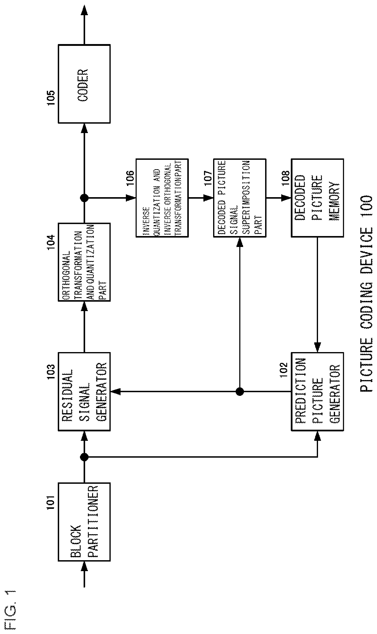
[0037]FIG. 1 is a block diagram of the picture coding device 100 according to the first embodiment. FIG. 1 shows only a data flow related to a picture signal and shows no data flow related to supplementary information such as a motion vector and a prediction mode other than the picture signal. A picture signal for at least one frame is input to the picture coding device 100.

[0038]A block partitioner 101 partitions a picture into coding target blocks that are each subjected to a coding process and supplies a picture signal in the coding target blocks to a residual signal generator 103. Further, the block partitioner 101 supplies the picture signal of the coding target blocks to a prediction picture generator...

second embodiment

[0121]A description will be given of a picture coding device and a picture decoding device according to the second embodiment of the present disclosure. According to the second embodiment, block partitioning is restricted when the depth of block partitioning reaches a limit depth. The other configurations are the same as according to the first embodiment; therefore, no description will be given of the other configurations.

[0122]A description will be given below of the depth of block partitioning. According to the first embodiment, the process of partitioning the block into two or three and then recursively partitioning each of the two or three blocks obtained by partitioning into two or three has been described. For this process, a first process of partitioning into two or three is defined as depth 0. Further, a second process of partitioning each of the two or three blocks obtained by the first process of partitioning into two or three is defined as depth 1, a third process of part...

third embodiment

[0136]A description will be given of a picture coding device and a picture decoding device according to the third embodiment of the present disclosure. According to the third embodiment, block partitioning is controlled on the basis of the number of pixels located beyond the picture boundary. The other configurations are the same as according to the first embodiment; therefore, no description will be given of the other configurations.

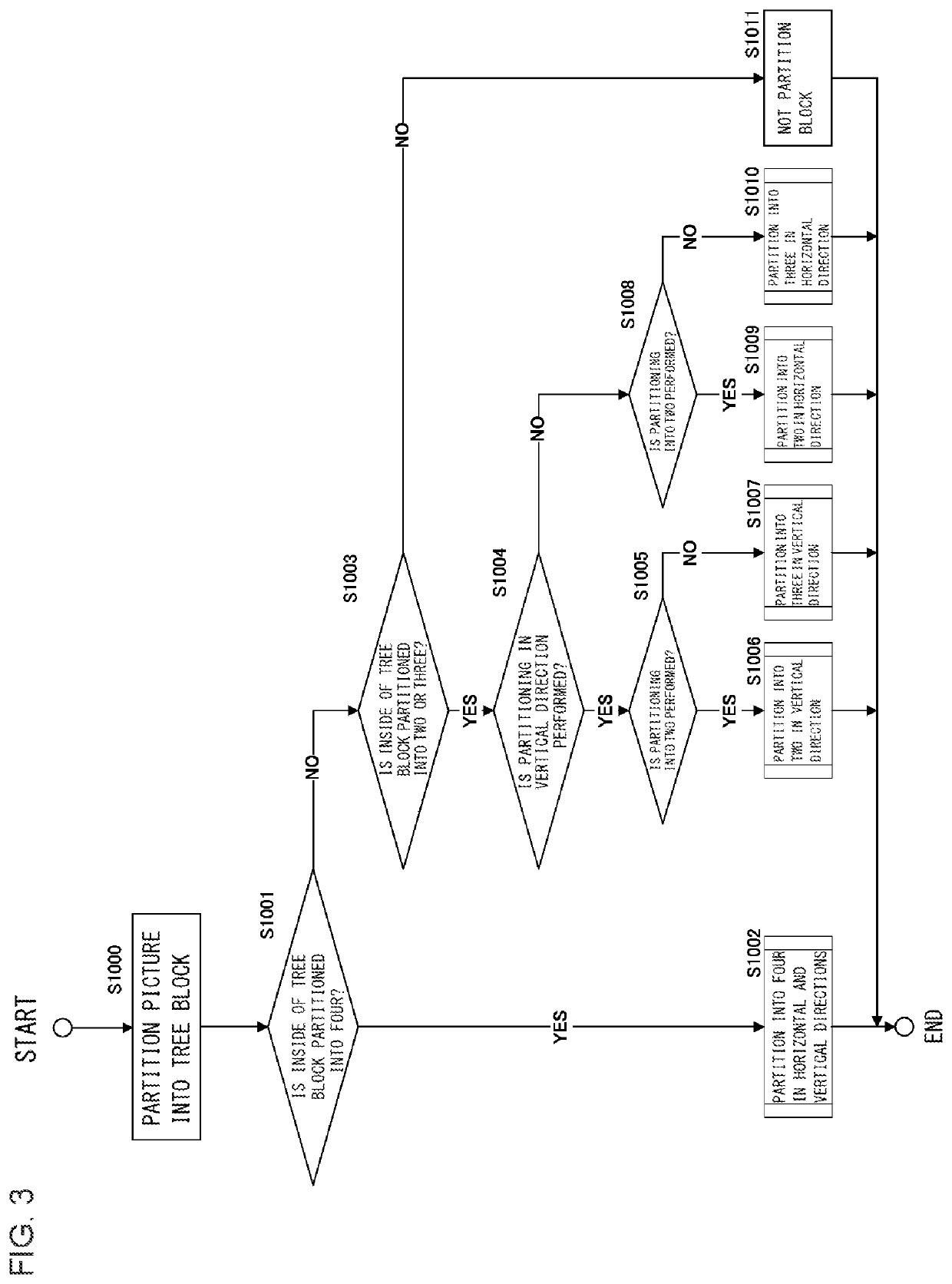
[0137]The control on block partitioning is applied to partitioning of a block located at the frame end into two or three. That is, the process of partitioning into two or three (S1004 to S1010) shown in FIG. 3 is replaced with a process described below. Further, the process of partitioning into two or three (S1104 to S1110) shown in FIG. 7 is replaced with the process described below. Further, the process of partitioning into two or three (S1202 to S1208) shown in FIG. 8 is replaced with the process described below.

[0138]A description will be given of t...


PUM


Abstract

A block partitioner includes a quad splitter structured to partition a target block obtained by recursive partitioning in half in both a horizontal direction and a vertical direction to generate four blocks, and a binary / ternary splitter structured to partition the target block obtained by recursive partitioning into two or three in the horizontal direction or the vertical direction to generate two or three blocks, and the binary / ternary splitter disallows partitioning of the target block in the horizontal direction when partitioning of the target block in the horizontal direction causes the target block obtained by partitioning to be located beyond a right side of a picture boundary, and disallows partitioning of the target block in the vertical direction when partitioning of the target block in the vertical direction causes the target block obtained by partitioning to be located beyond a lower side of the picture boundary.

Description

BACKGROUND OF THE INVENTION1. Field of the Invention[0001]The present disclosure relates to a technique for coding and decoding a picture in units of blocks obtained by partitioning.2. Description of the Related Art[0002]A picture is partitioned into blocks each containing a predetermined number of pixels, and picture coding and decoding is performed on a block-by-block basis. Herein, partitioning in appropriate units of blocks allows increases in efficiency of intra-frame prediction, inter-frame prediction, orthogonal transformation, entropy coding, and the like, thereby leading to an increase in coding efficiency.[0003][Patent Literature 1] JP2015-526008 A[0004][Non Patent Literature 1] JVET, Versatile Video Coding (Draft 2), July 2018SUMMARY OF THE INVENTION[0005]When a block is not partitioned into blocks of an appropriate size and shape, the coding efficiency will decrease. In particular, at a frame end, a block containing pixels located beyond a picture boundary has an inappro...

Claims


Application Information

Patent Timeline
IPC IPC(8): H04N19/119H04N19/176H04N19/167
CPCH04N19/119H04N19/167H04N19/176H04N19/70H04N19/172H04N19/96H04N19/107
Inventor KURASHIGE, HIROYUKI
Owner JVC KENWOOD CORP A CORP OF JAPAN
Why Eureka
Try Eureka