Vehicle unit installation structure

a technology for installing structures and vehicles, applied in the direction of electric propulsion mounting, vehicle sub-unit features, battery/cell propulsion, etc., can solve the problems of large front overhang and small crush strok

Active Publication Date: 2021-09-09
TOYOTA JIDOSHA KK
View PDF15 Cites 2 Cited by
  • Summary
  • Abstract
  • Description
  • Claims
  • Application Information

AI Technical Summary

Benefits of technology

[0020]As described above, in accordance with present disclosure, the crush stroke can be ensured even if the power generating unit and the driving unit are disposed so as to be lined-up in the vehicle longitudinal direction.

Problems solved by technology

However, because both the generator and the engine are members that are hard to crush, when these members are lined-up in the vehicle longitudinal direction, the crush stroke is small at the time when the vehicle is involved in a front collision.
Even so, if an attempt is made to ensure the crush stroke, the front overhang becomes large.

Method used


Image

  • Vehicle unit installation structure
  • Vehicle unit installation structure
  • Vehicle unit installation structure

Examples


modified example

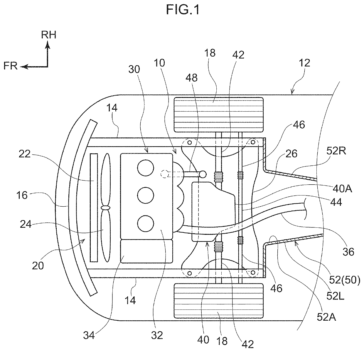
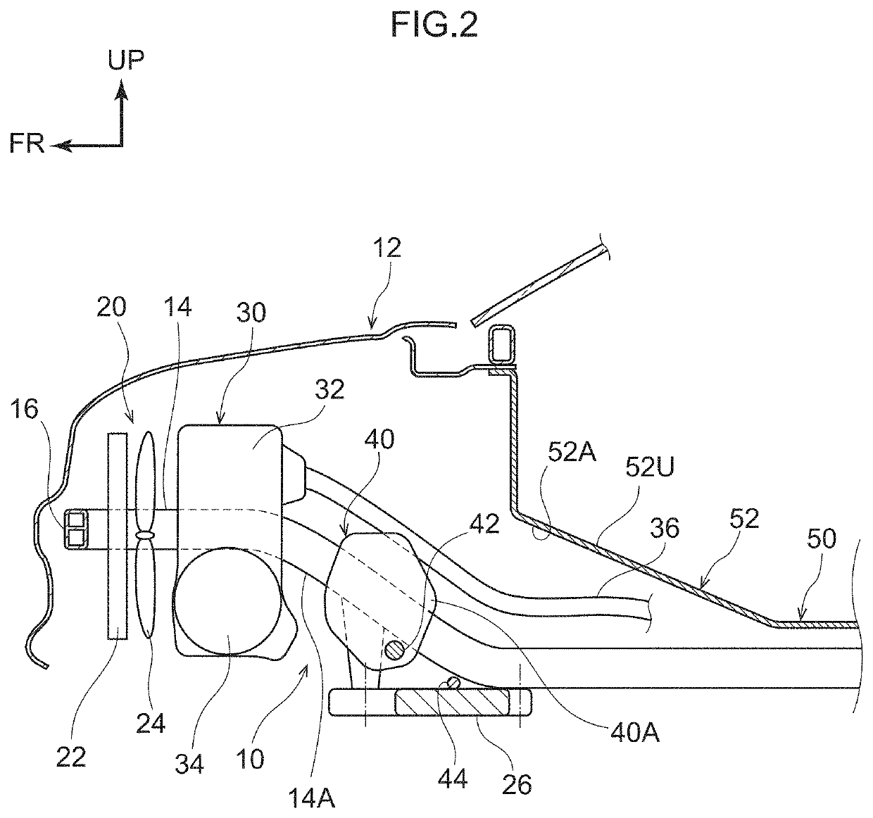
[0048]As shown in FIG. 5, the power generating unit 30 may be a fuel cell stack 38. In this case as well, at the time of a front collision of the vehicle 12, operation that is similar to that described above is obtained. Namely, the crush stroke can be ensured in a fuel cell vehicle that serves as the vehicle 12.

[0049]Further, the vehicle 12 of the present embodiment can be easily switched between an electric vehicle and a fuel cell vehicle merely by switching the engine 32 and the generator 34, and the fuel cell stack 38. Namely, because the power generating unit 30 and the driving unit 40 are separate, the fuel cell stack 38, which has plural fuel cells that are susceptible to vibrations of the motor for driving, also can be installed in the vehicle 12.

[0050]Although the vehicle unit installation structure 10 relating to the present embodiment has been described above on the basis of the drawings, the vehicle unit installation structure 10 relating to the present embodiment is not...


PUM


Abstract

A vehicle unit installation structure has: a power generating unit that is installed at a front portion of a vehicle; a driving unit that is installed at a vehicle rear side of the power generating unit, and that drives front wheels of the vehicle; and a floor tunnel that is formed at a floor that is disposed at a vehicle rear side of the driving unit, a width of a front end portion of the floor tunnel being greater than a width of at least a rear end portion of the driving unit.

Description

CROSS-REFERENCE TO RELATED APPLICATION[0001]This application is based on and claims priority under 35 USC 119 from Japanese Patent Application No. 2020-039225 filed on Mar. 6, 2020, the disclosure of which is incorporated by reference herein.BACKGROUNDTechnical Field[0002]The present disclosure relates to a vehicle unit installation structure.Related Art[0003]There is conventionally known a vehicle in which a generator is installed. This vehicle has a generator, an engine that drives the generator, and a motor that drives the driving wheels. The generator and the engine are disposed so as to be lined-up in the vehicle longitudinal direction (see, for example, Japanese Patent Application Laid-Open (JP-A) No. 2019-107962).[0004]However, because both the generator and the engine are members that are hard to crush, when these members are lined-up in the vehicle longitudinal direction, the crush stroke is small at the time when the vehicle is involved in a front collision. Even so, if an...

Claims


Application Information

Patent Timeline
Patent Type & Authority Applications(United States)
IPC IPC(8): B62D25/20B60K6/24B60K6/26B60L50/70
CPCB62D25/20B60K6/24B60Y2200/92B60L50/70B60K6/26B60K1/00B62D25/2009B60L50/71B60L50/72Y02T90/40B60K6/46B60K6/40B60Y2306/01B60K2001/001H01M2250/20Y02E60/50Y02T10/62
Inventor AJISAKA, SATOSHI
Owner TOYOTA JIDOSHA KK
Why Eureka
Try Eureka