
Cruise missile weapon active hazard mitigation system

a technology cruise missile, which is applied in the field of active hazard mitigation system of cruise missile, can solve the problems of cruise missile thermal threat, collateral damage to weapon platforms, logistic systems, personnel, etc., and minimize the probability of uncontrolled initiation and subsequent collateral damage.

Active Publication Date: 2021-09-09
RAYTHEON CO
View PDF0 Cites 0 Cited by
  • Summary
  • Abstract
  • Description
  • Claims
  • Application Information

AI Technical Summary

Benefits of technology

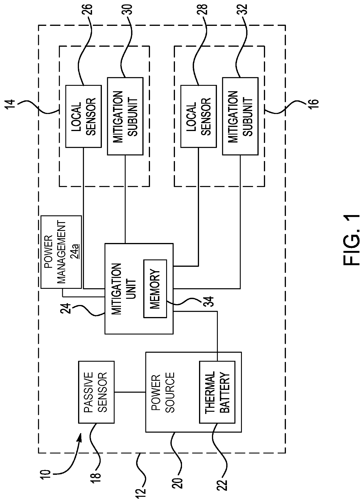
The mitigation control system described in this patent is designed to minimize the likelihood of accidental threats causing damage to weapon platforms, logistic systems, and personnel. The system uses a hybrid sensor system with both passive and active sensors to detect thermal threats in an environment containing an energetic material. The system analyzes the environment and can predict when a mitigation event is likely to occur. The system can initiate a mitigation response, such as a linear shape charge, to protect against the threat. The system is effective and complies with military standards while being implemented in a launch system that does not hinder the mitigation actions. Overall, this system provides effective mitigation and reduced damage to protect against unplanned stimuli.

Problems solved by technology

During operation, such as during execution of a mission, the environment containing the energetic material may be subject to external and unplanned stimuli.
For example, a cruise missile may be subject to a thermal threat when the weapon is unexpectedly impacted.
The responses may cause collateral damage to weapon platforms, logistic systems, and personnel.
Providing mitigation in some environments, such as in integrated weapon systems, is difficult due to the complexity of providing a mitigation solution for each sub-assembly which contains unique components and has different characteristics relative to the other sub-assemblies.
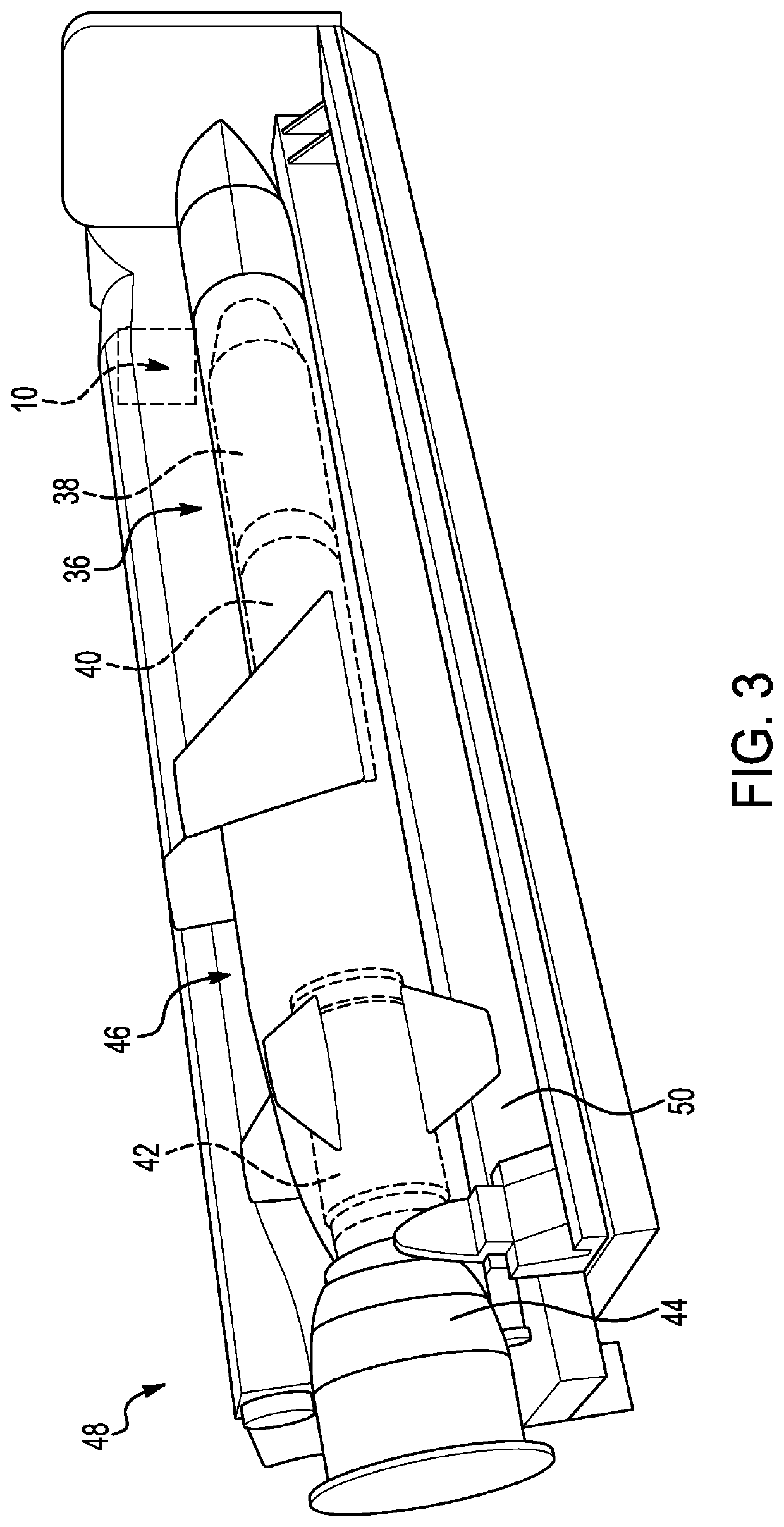
Launch systems in which the weapon is stored in a canister also present challenges in mitigation due to the impact of the canister when detecting thermal threats.

Method used


Image

  • Cruise missile weapon active hazard mitigation system
  • Cruise missile weapon active hazard mitigation system
  • Cruise missile weapon active hazard mitigation system

Examples


Embodiment Construction

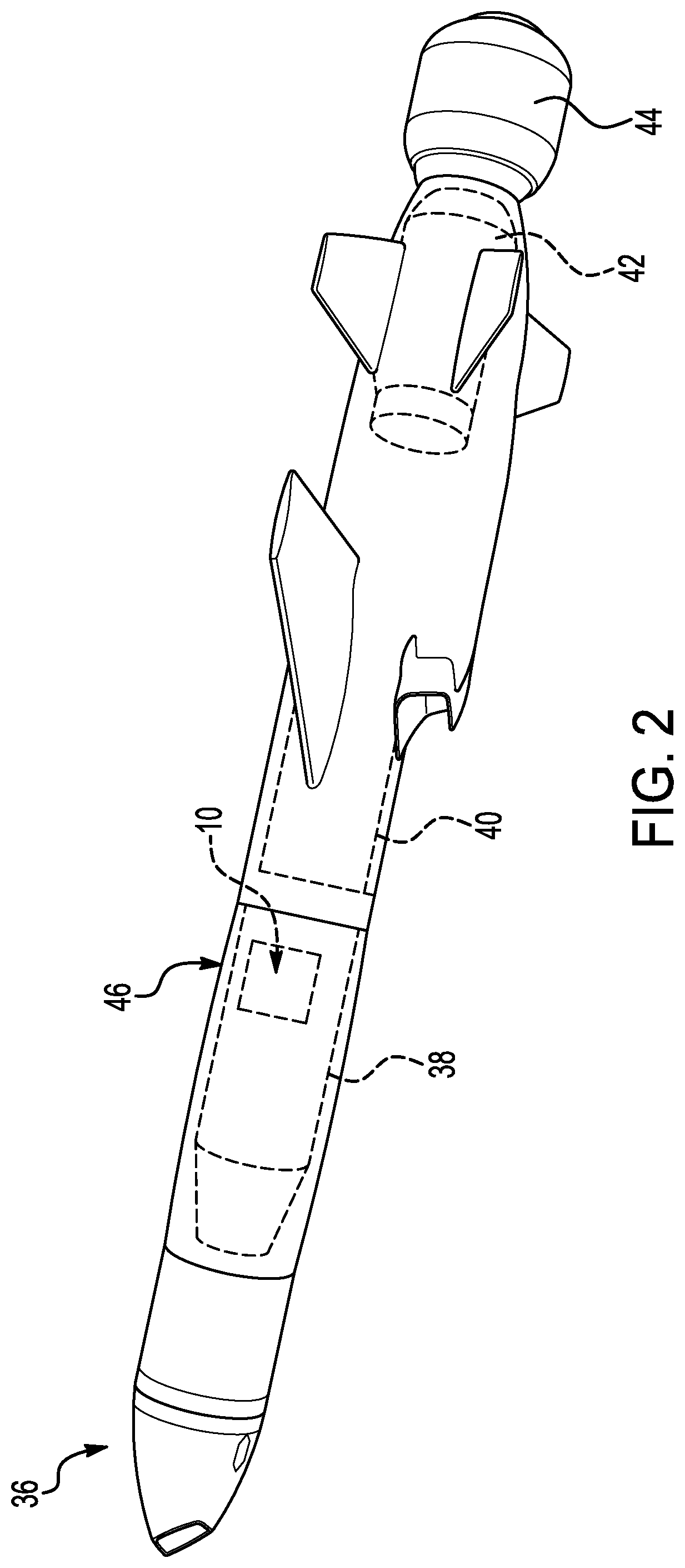
[0042]The principles described herein have application in any environment that contains an energetic material and requires a mitigation action or technique to control a reaction of the energetic material when subject to a thermal threat. Energetic materials include materials that are able to release stored chemical energy. Exemplary materials include explosives, pyrotechnic compositions, propellants, and other fuel or oxidizer mixtures. Suitable platforms that may include an energetic material and a mitigation control system for the energetic material include air, land, space, and sea vehicles in defense applications or other military applications. The platform may be stationary or moving. Manned or unmanned platforms may be suitable. Weapons including cruise missiles are suitable platforms. Other exemplary applications include transportation systems and vehicles, communication-type applications, and laboratory environments.

[0043]Referring first to FIG. 1, a mitigation control syste...


PUM


Abstract

A mitigation control system is arranged in an environment containing an energetic material and includes an abnormal temperature sensor for detecting an abnormal temperature of the environment, a power source that is mechanically actuated by the abnormal temperature sensor when the abnormal temperature exceeds a predetermined abnormal temperature threshold, a mitigation controller that is actuated by the power source, and a plurality of local temperature sensors that are communicatively coupled to the mitigation controller and are arranged for detecting critical temperatures in specific regions of the environment. The mitigation controller executes a mitigation action when one of the critical temperatures exceeds a predetermined critical temperature threshold for the corresponding specific region.

Description

FIELD OF THE INVENTION[0001]The invention relates to a system and method for mitigating hazardous reactions when an environment containing an energetic material is subject to unplanned stimuli.DESCRIPTION OF THE RELATED ART[0002]Various applications may use energetic materials that are able to release stored chemical energy. Examples of environments in which energetic materials are contained include weapon systems, such as cruise missiles, and other transportation systems. During operation, such as during execution of a mission, the environment containing the energetic material may be subject to external and unplanned stimuli. For example, a cruise missile may be subject to a thermal threat when the weapon is unexpectedly impacted. When subject to the unplanned stimuli, a violent energetic response from the energetic material in the environment may occur. The responses may cause collateral damage to weapon platforms, logistic systems, and personnel.[0003]In military applications, in...

Claims


Application Information

Patent Timeline
Patent Type & Authority Applications(United States)
IPC IPC(8): F42B15/34F41A17/06
CPCF42B15/34F41A17/06F42B39/20F42B39/14F42B39/16F42B39/18F41F3/06Y02E60/10H01M10/613H01M10/625F42B12/207F42B15/36G01K3/005H01M10/486F42C15/00
Inventor BARENTS, DENNIS D.CHRISTIANSON, KIM L.LATTIMORE, AARON C.KNIGHT, ANDREW K.
Owner RAYTHEON CO
Learn More