LED driving circuit

a driving circuit and driving circuit technology, applied in the direction of lighting apparatus, lighting sources, electrical equipment, etc., can solve the problems of lighting flicker created by a large ripple current (such as a 30% ripple) and the output current is not really constant, and the ripple at the output is hardly avoidabl

Active Publication Date: 2021-09-09
SIGNIFY HLDG BV
View PDF0 Cites 0 Cited by
  • Summary
  • Abstract
  • Description
  • Claims
  • Application Information

AI Technical Summary

Benefits of technology

[0054]when splitting the input current into two non-zero currents, controlling a current ratio between the two non-zero currents thereby to control the overall output color or color temperature.

Problems solved by technology

The output current is not really constant, and there is a trade off between the cost of the driver components and the quality of the current drive signals.
Especially when the driver is a single stage driver, the PFC requirement of the driver make the ripple at the output hardly avoidable.
Thus, the lighting flicker created by a large ripple current (such as a 30% ripple) is becoming unacceptable.
There is therefore a need to reduce the light flicker, resulting from a level of current ripple, but with a minimal cost increase and efficiency penalty.
If a smaller amount of flicker is needed, a driver with lower ripple (and hence higher cost) is necessary.
If a ripple absorbing circuit is provided, for example within a linear current source circuit, this will cause power loss.

Method used


Image

  • LED driving circuit
  • LED driving circuit
  • LED driving circuit

Examples


Embodiment Construction

[0067]The invention will be described with reference to the Figures.

[0068]It should be understood that the detailed description and specific examples, while indicating exemplary embodiments of the apparatus, systems and methods, are intended for purposes of illustration only and are not intended to limit the scope of the invention. These and other features, aspects, and advantages of the apparatus, systems and methods of the present invention will become better understood from the following description, appended claims, and accompanying drawings. It should be understood that the Figures are merely schematic and are not drawn to scale. It should also be understood that the same reference numerals are used throughout the Figures to indicate the same or similar parts.

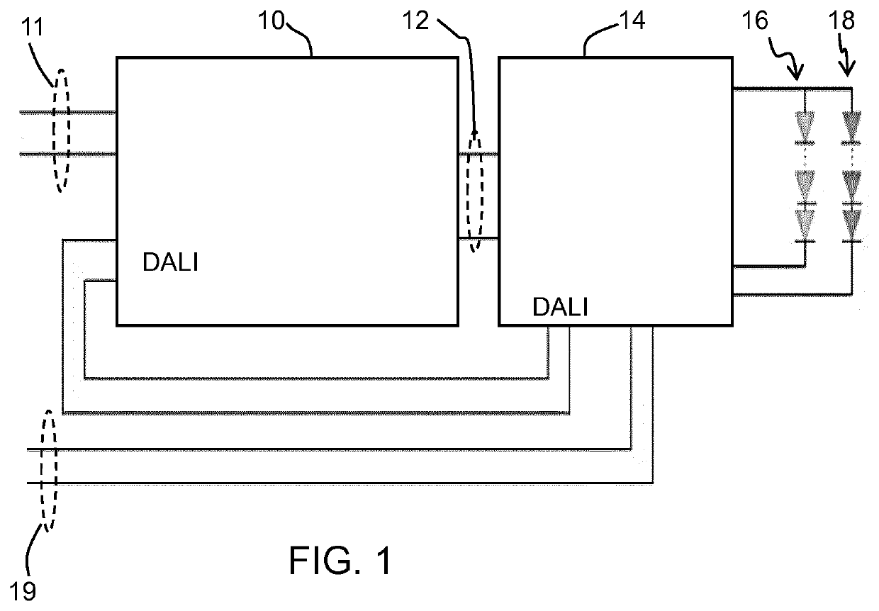
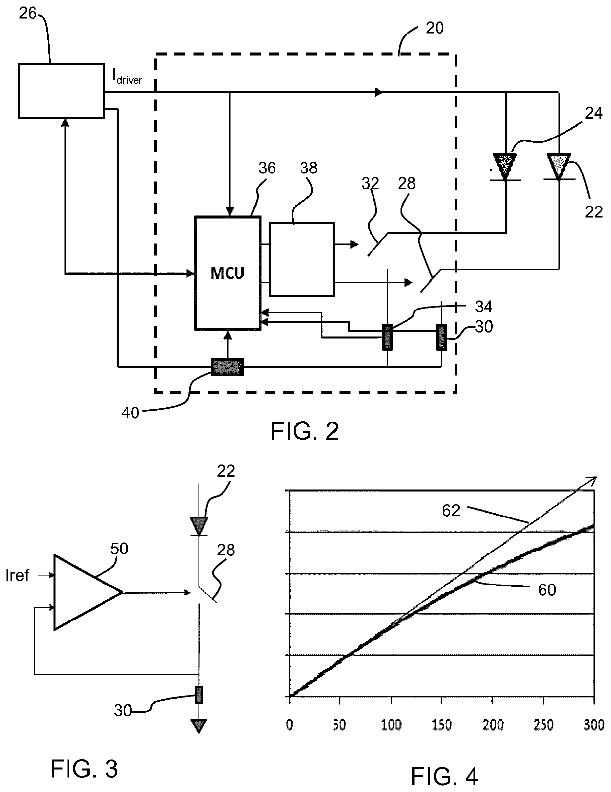
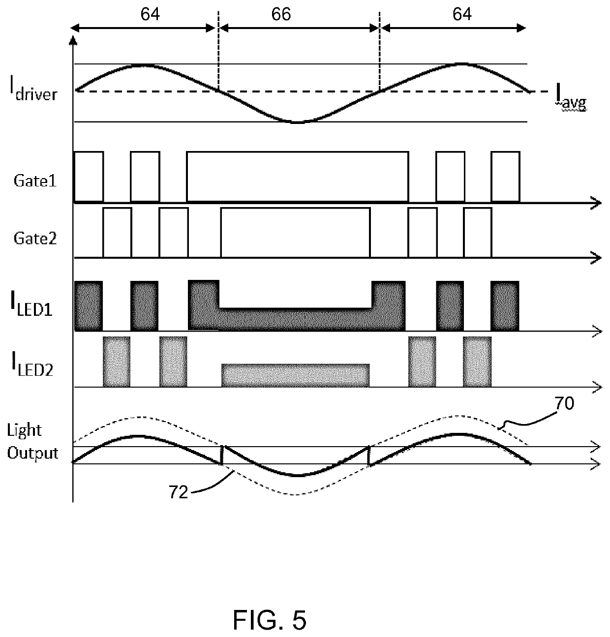
[0069]The invention provides a LED driving circuit for driving at least two LED segments, using an input current which has a current ripple. The circuit comprises a current distributing circuit which provides the input cur...


PUM

PropertyMeasurementUnit
frequencyaaaaaaaaaa
frequencyaaaaaaaaaa
frequencyaaaaaaaaaa

Abstract

A LED driving circuit (20) is for driving at least two LED segments (22, 24) of different color or color temperature, using an input current which has a current ripple amplitude. The LED driving circuit (20) comprises an input to receive the input current; an output to connect to the at least two LED segments (22, 24); and a current distributing circuit which provides the input current to a single one of the two LED segments when the current is at a peak portion, wherein the current distributing circuit is adapted, when providing the input current to a single one of the two LED segments during the peak portion, to provide the input current to the single one of the two LED segments alternately, and splits the input current into two non-zero currents for different LED segments when the current is in a trough. When all current is provided to one LED segment, the light conversion efficiency is lower than when two segments are driven with lower current. This means the effect which the current ripple has on the light output is reduced. The driving circuit effectively compensates for the current ripple by adjusting the light conversion efficiency so that a flatter light output characteristic is obtained.

Description

FIELD OF THE INVENTION[0001]This invention relates to LED driving circuits and lighting arrangements using the LED driving circuit.BACKGROUND OF THE INVENTION[0002]LEDs are increasingly used in current lighting applications, and increasingly low cost LED drivers are available for applying the desired constant drive current to the LEDs.[0003]The output current is not really constant, and there is a trade off between the cost of the driver components and the quality of the current drive signals. There is always a ripple over the average current value.[0004]Based on current standards, a 30% ripple at the (rectified) mains frequency (100 Hz or 120 Hz) is acceptable, and LED drivers are designed to approach this limit of acceptability, in order to limit the driver cost. Especially when the driver is a single stage driver, the PFC requirement of the driver make the ripple at the output hardly avoidable.[0005]However, customer requirements are for increasing light uniformity, especially in...

Claims


Application Information

Patent Timeline
Patent Type & Authority Applications(United States)
IPC IPC(8): H05B45/36H05B45/20H05B45/395H05B45/325H05B44/00
CPCH05B45/36H05B45/325H05B45/395H05B45/20H05B45/24H05B47/18
Inventor SHI, LIANGFU, JIEWANG, KELVIN
Owner SIGNIFY HLDG BV
Why Eureka
Try Eureka