
Liquid crystal panel module, backlight module and liquid crystal display

Active Publication Date: 2011-08-04
CM VISUAL TECH CORP +2
View PDF18 Cites 38 Cited by
  • Summary
  • Abstract
  • Description
  • Claims
  • Application Information

AI Technical Summary

Benefits of technology

[0008]The invention is directed to a liquid crystal panel module, which can resolve problems of color shift, brightness reduction and gray level inversion.
[0009]The invention is directed to a backlight module, which can resolve a problem of low light utilization efficiency.
[0010]The invention is directed to a liquid crystal display (LCD), which can resolve problems of color shift, brightness reduction and gray level inversion of a liquid crystal panel module, or resolve a problem of low light utilization efficiency of a backlight module.
[0029]According to the above descriptions, in the liquid crystal panel module of the invention, multi-order diffraction light is used to compensate the problem of color shift under a large viewing angle, and the diffraction grating layer can be used to collimate the large-angle incident light provided by the backlight module. Moreover, the backlight module of the invention can pull straight the obliquely emitted light to improve light utilization efficiency. The LCD of the invention can simultaneously or individually use the aforementioned liquid crystal panel module and the backlight module.

Problems solved by technology

However, the wide viewing film used by the TN LCD is expensive, and the MVA LCD has problems of complicated fabrication process, long fabrication time, high cost, low aperture ratio and low process yield.
Moreover, since light emitting directions of backlight modules used by the LCD are inconsistent, light utilization efficiency thereof is low.
Especially, a great part of the light provided by the backlight module with a side light-incident design cannot orthogonally enter the liquid crystal panel.
When a consumer read a private letter or data through the LCD in the public place, the private data can be peeped by others and is probably leaked out.

Method used


Image

  • Liquid crystal panel module, backlight module and liquid crystal display
  • Liquid crystal panel module, backlight module and liquid crystal display
  • Liquid crystal panel module, backlight module and liquid crystal display

Examples


Embodiment Construction

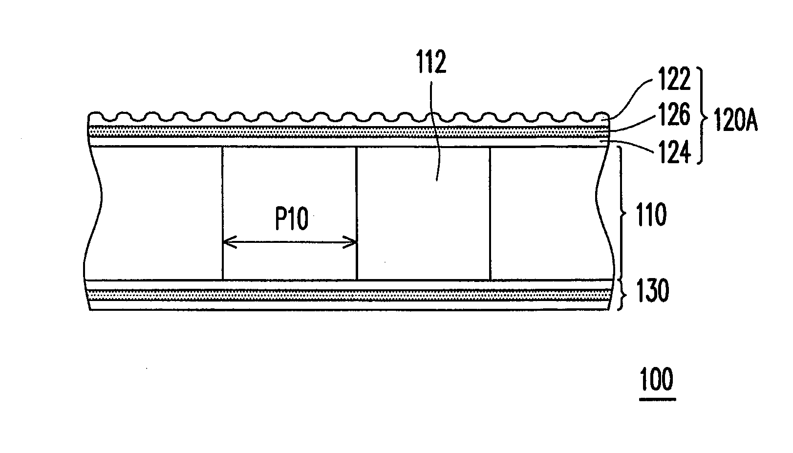
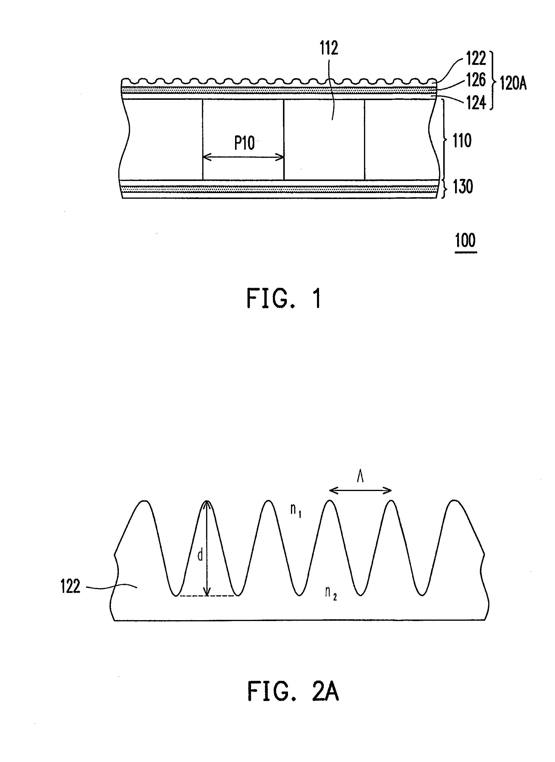
[0049]FIG. 1 is a schematic diagram illustrating a liquid crystal panel module according to an embodiment of the invention, and FIG. 2A is a partial enlarged view of a diffraction grating layer of the liquid crystal panel module of FIG. 1. Referring to FIG. 1 and FIG. 2A, the liquid crystal panel module 100 of the present embodiment includes a liquid crystal panel 110 and a diffraction grating layer 122. The liquid crystal panel 110 has a plurality of pixels 112. The diffraction grating layer 122 is disposed on the liquid crystal panel 110, and a maximum period Λ of a grating of the diffraction grating layer 122 is smaller than 1 / 10 of a size P10 of the pixels 112.

[0050]According to principles of optics, based on undulatory of light, the light can be diffracted by a micro structure, namely, when a normal incident light passes through the diffraction grating layer 122, a part of the light is bended to up and down directions. In other words, the normal light emitted from the liquid cr...


PUM


Abstract

A liquid crystal panel module, a backlight module and a liquid crystal display (LCD) are provided. The liquid crystal panel module includes a liquid crystal panel and a diffraction grating layer. The liquid crystal panel has a plurality of pixels. The diffraction grating layer is disposed on the liquid crystal panel, and a maximum period of a grating of the diffraction grating layer is smaller than 1 / 10 of a size of the pixels. The backlight module includes a light guide plate, a light emitting element and a diffraction grating film. A light provided by the light emitting element emits from a light emitting surface of the light guide plate and is bended towards the light emitting element after passing through the diffraction grating film. The liquid crystal panel module and the backlight module can be applied to the LCD together or individually.

Description

CROSS-REFERENCE TO RELATED APPLICATION[0001]This application claims the priority benefit of Taiwan application serial no. 99103358, filed on Feb. 4, 2010. The entirety of the above-mentioned patent application is hereby incorporated by reference herein and made a part of specification.BACKGROUND[0002]1. Field of the Invention[0003]The invention relates to a panel module, a light source module and a display device. Particularly, the invention relates to a liquid crystal panel module, a backlight module, and a liquid crystal display.[0004]2. Description of Related Art[0005]Presently, performance requirements for liquid crystal displays (LCDs) in the market are high contrast, no gray level inversion, small color shift, high brightness, high color richness, high color saturation, fast response speed, and wide viewing angle, etc. A liquid crystal material is a high efficiency refractive index modulation material. An optical path difference of a normal light and an oblique light penetrati...

Claims


Application Information

Patent Timeline
IPC IPC(8): G02F1/1335F21V8/00
CPCG02F1/1335G02F1/133504G02F2201/305G02B5/1809
Inventor LI, WANG-YANGLIN, HUNG-YUCHANG, HSIN-WENLIANG, YI-PANWANG, CHIEN-CHIHLEE, WAI-HONTSAI, HUAI-FANG
Owner CM VISUAL TECH CORP
Learn More