Sleeve assemblies and methods of fabricating same

Active Publication Date: 2021-09-16
GENERAL ELECTRIC CO
View PDF0 Cites 0 Cited by
  • Summary
  • Abstract
  • Description
  • Claims
  • Application Information

AI Technical Summary

Benefits of technology

[0006]In one aspect, a sleeve assembly for a combustion system is provided. The sleeve assembly includes a first duct including a first circumferential surface and a second duct including a second circumferential surface. The first circumferential surface radially overlaps the second circumferential surface such that the first duct and the second duct collectively define a continuous combustion chamber therein. The continuous combustion chamber is configured to receive high temperature gases flowing therethrough. The sleeve assembly further includes a wear insert removably coupled to the first circumferential surface and extending radially therefrom to engage the second circumferential surface.
[0007]In another aspect, a turbine assembly is provided. The turbine assembly includes a compressor section, a turbine section coupled downstream of the compressor section, and a combustor. The combustor includes a plurality of cans coupled in flow communication between the compressor section and the turbine section. A first can of the plurality of cans includes a sleeve assembly. The sleeve assembly includes a first duct including a first circumferential surface and a second duct including a second circumferential

Problems solved by technology

As a result, at least some such assemblies may be prone to wear at the interface defined between the liner and the transition duct.
However, applying these spray coatings general

Method used


Image

  • Sleeve assemblies and methods of fabricating same
  • Sleeve assemblies and methods of fabricating same
  • Sleeve assemblies and methods of fabricating same

Examples


Example

[0015]Unless otherwise indicated, the drawings provided herein are meant to illustrate features of embodiments of this disclosure. These features are believed to be applicable in a wide variety of systems comprising one or more embodiments of this disclosure. As such, the drawings are not meant to include all conventional features known by those of ordinary skill in the art to be required for the practice of the embodiments disclosed herein.

DETAILED DESCRIPTION

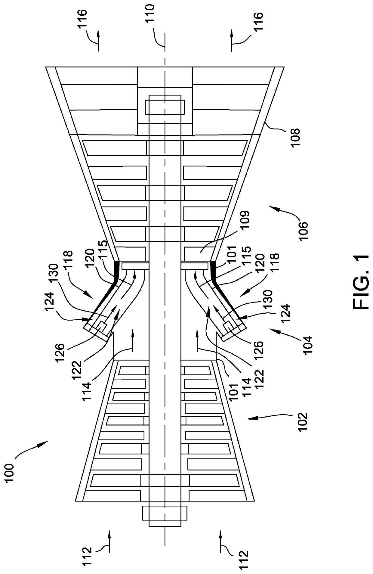
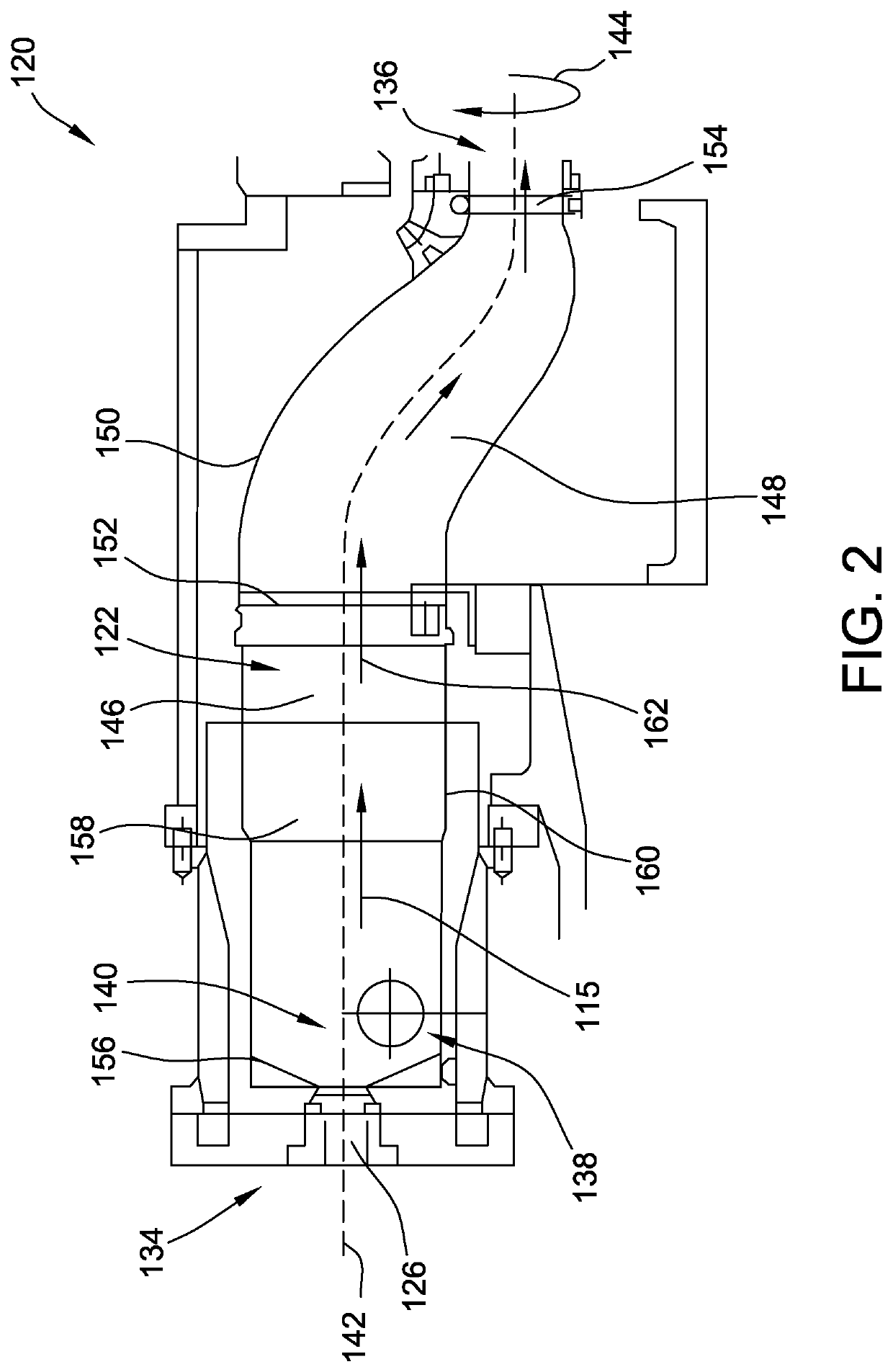
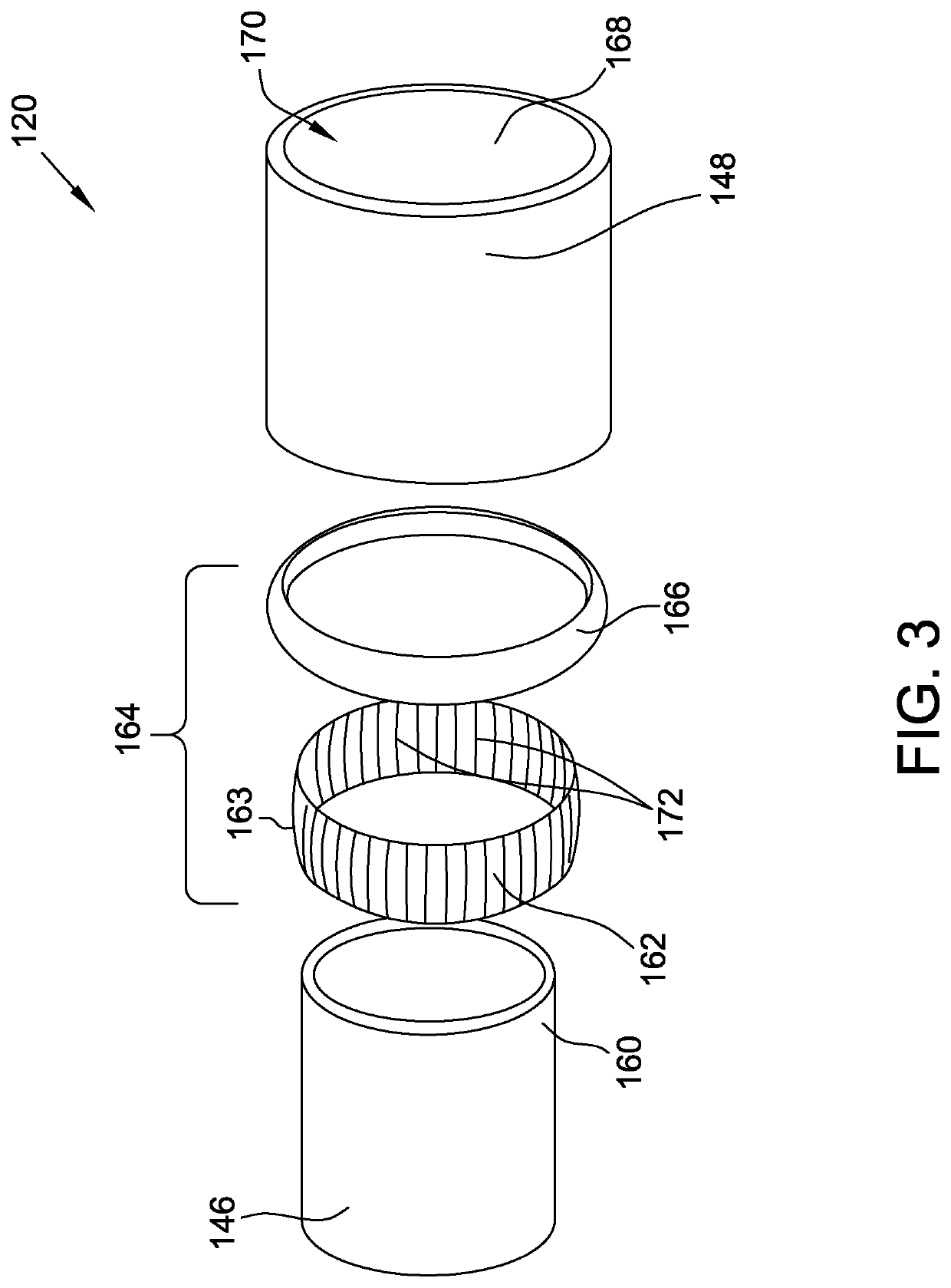
[0016]The exemplary systems and methods described herein overcome at least some disadvantages of known sleeve assemblies by providing a wear insert that is removably coupled to at least a portion one duct of the sleeve assembly to facilitate reducing abrasion resistance at the sliding interface within the sleeve assembly. More specifically, the embodiments described herein include a first duct having a first circumferential surface, a second duct having a second circumferential surface, and a wear insert that extends circumfer...


PUM


Abstract

A sleeve assembly for a combustion system includes a first duct including a first circumferential surface and a second duct including a second circumferential surface. The first circumferential surface radially overlaps the second circumferential surface such that the first duct and the second duct collectively define a continuous combustion chamber therein. The continuous combustion chamber is configured to receive high temperature gases flowing therethrough. The sleeve assembly further includes a wear insert removably coupled to the first circumferential surface and extending radially therefrom to engage the second circumferential surface.

Description

BACKGROUND[0001]The field of this disclosure relates generally to sleeve assemblies and, more particularly, to sleeve assemblies for use with a combustor.[0002]At least some known turbine assemblies include a compressor, a combustor, and a turbine coupled together in a serial flow arrangement. Gas flowing into the compressor is compressed and discharged into the combustor where it is mixed with fuel. The resulting mixture is ignited to generate combustion gases that are channeled from the combustor through the turbine. The gases drive the turbine, which in turn, may power an electrical generator coupled to the turbine.[0003]At least some known combustors include a sleeve assembly that includes a liner and a transition duct that collectively define a combustion chamber in which the mixture of fuel and compressed gas is ignited prior to it being supplied to a turbine coupled to the transition duct. Known sleeve assemblies generally permit axial movement between the transition duct and...

Claims


Application Information

Patent Timeline
IPC IPC(8): F23R3/60F02C7/28F23R3/46F23R3/00
CPCF23R3/60F02C7/28F23R3/46F23R2900/00005F23R2900/00012F05D2240/55F23R3/002F23R3/00F02C3/06F23R2900/00017F01D9/023
Inventor KIDDER, KYLE LEECZIRLE, ZSOLT
Owner GENERAL ELECTRIC CO
Why Eureka
Try Eureka