Inspiratory resistor valve system with expiratory port

a resistor valve and inspiratory technology, applied in the field of inspiratory resistor valve systems with expiratory ports, can solve the problems of less effective or ineffective, and achieve the effects of reducing intrathoracic pressure, preventing respiratory, and increasing blood volum

Active Publication Date: 2021-09-23
VITALINC LLC
View PDF0 Cites 1 Cited by
  • Summary
  • Abstract
  • Description
  • Claims
  • Application Information

AI Technical Summary

Benefits of technology

[0003]Embodiments of the present invention are directed to devices that increase the blood flow to a patient's chest during the recoil phase of CPR and during spontaneous respiration. In particular, embodiments are directed to inspiratory resistor valve systems with expiratory ports (IRVs) that have an inspiratory port and a separate expiratory port to prevent expiratory gases from being mixed with inspiratory gases, thus separating inflow from outflow and allowing for the delivery of higher concentrations of O2 to the patient during CPR. Additionally, embodiments provide an exit flow path for any fluids, such as those resulting from pulmonary edema, that directs such fluids out of the IRV and away from the inspiratory flow path of the IRV. In this regard backflow protection can be desirable to help maintain the integrity of fluid sensitive valving mechanisms. In some embodiments expiratory gases pass through a filter contiguous with the expiratory port to protect rescue personnel from potential pathogens, including viral particles. In some embodiments one or more sensors are located within the IRV and between the inspiratory and expiratory flow ports.
[0006]In another embodiment, an inspiratory resistor valve system (IRV) may include a housing having an upper region, a lower region, and an expiratory region. The IRV may include a first pressure-responsive one-way valve disposed between the upper region and the lower region for allowing for positive pressure ventilation with less than 5 cm H2O resistance and for preventing all respiratory gases from flowing from the upper region to the lower region when a pressure in the lower region is sub-atmospheric. The IRV may include a second pressure-responsive valve disposed between the upper region and the lower region that remains closed until the pressure in the lower region falls below a threshold level, causing the second pressure responsive valve to open to allow the respiratory gases to flow to the patient's lungs due to a pressure differential between atmospheric pressure and the pressure in the lower region. The IRV may include a third pressure-responsive valve disposed between the upper region and the expiratory region for preventing all expiratory fluids from flowing to the upper region when the pressure in the thorax is greater than atmospheric pressure. The IRV may include a fourth pressure-responsive valve in the expiratory region that occludes when pressure in the lower region interfacing with the patient is below atmospheric pressure and opens when pressure in the lower region interfacing with the patient is above atmospheric pressure.
[0007]In some embodiments, the threshold level may be between about −5 and −20 cm of water. The IRV may include a physiological sensor disposed within one or both of the upper region and the lower region. The IRV may include a communications interface that transmits signals from the physiological sensor to one or both of a ventilation device and a compression device. The IRV may include a filter interfaced with the expiratory region. The second pressure-responsive valve may include a duck-bill valve having an outer surface that selectively engages a valve seat. The duck-bill valve may open to enable inspiratory flow to be delivered to the patient while the outer surface engages the valve seat to occlude the expiratory region from the upper region. The duck-bill valve may close and the outer surface may move away from the valve seat to expel the expiratory fluids from the IRV and to prevent the expiratory fluids from flowing to the upper region.
[0008]In another embodiment, an inspiratory resistor valve system (IRV) may include a housing, a ventilation port that is configured to interface with a ventilation device, and a patient port that is configured to interface with a patient interface device. The IRV may include a separate expiration port and a positive pressure ventilation flow path that is in fluid communication with the ventilation port and the patient port. The positive pressure ventilation flow path may be configured to direct respiratory air from the ventilation port to the patient port. The IRV may include a patient inspiration flow path that is in fluid communication with the patient port. The patient inspiration flow path may be configured to deliver air to the patient port in the event of spontaneous inspiration of a patient. The IRV may include an expiration flow path that is in fluid communication with the patient port. The expiration flow path may be configured to direct expiratory fluids from the patient out of the IRV via the expiration port. The expiration flow path may be separated from at least a portion of the positive pressure ventilation flow path and the patient inspiration flow path via a series of pressure-responsive valves to separate inflow from outflow such that expiratory fluids are not mixed with inspiratory gases, thus resulting in delivery of higher concentrations of O2 to the patient during CPR.
[0010]During delivery of positive pressure ventilations, the first atmospheric pressure valve and the second atmospheric pressure valve may open while the first pressure-sensitive valve and the second pressure-sensitive valve may be closed. During spontaneous inspiration, the first pressure-sensitive valve and the second atmospheric pressure valve may be open, while the first atmospheric pressure valve and the second pressure-sensitive valve may be closed. During one or both of a chest compression phase of CPR and a patient expiration, the second pressure-sensitive valve may be open while the first atmospheric pressure valve, the first pressure-sensitive valve, and the second atmospheric pressure valve may be closed, thereby enabling respiratory fluids to exit the IRV without mixing with inspiratory gases. During a decompression phase of CPR, the first atmospheric pressure valve, the first pressure-sensitive valve, and the second pressure-sensitive valve may be closed, thereby lowering intrathoracic pressure and preventing respiratory gases from entering the patient and providing room for increased blood volume to return to the patient's heart during the decompression phase to increase circulation to the patient's coronary arteries and lower intracranial pressure.

Problems solved by technology

While conventional devices effectively provide increased negative pressure levels, problems can arise when fluid from the patient, such as that caused by pulmonary edema, passes from the patient's airway and into the valve or other device, thereby making them less effective or ineffective.

Method used


Image

  • Inspiratory resistor valve system with expiratory port
  • Inspiratory resistor valve system with expiratory port
  • Inspiratory resistor valve system with expiratory port

Examples


example

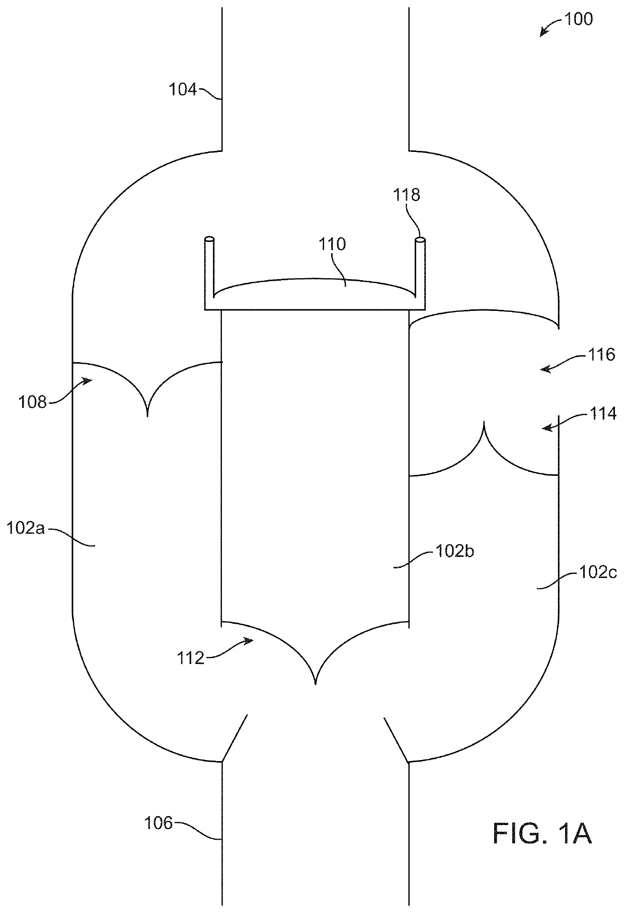
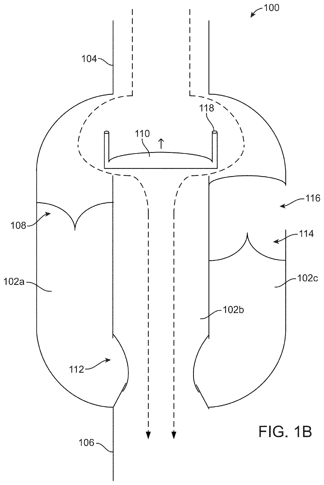
[0078]In an anesthetized pig, CPR was performed with an automated device that provides for compression and active decompression. A functional IRV, as described in this patent, that includes an inspiratory port and a separate expiratory port (similar to IRV 300), was attached to the endotracheal tube and pressures were measured with a pressure transducer at the level of the patient port. With each positive pressure breath airway pressures increased to approximately 20 mmHg and during each decompression phase they decreased to approximately −5 mmHg as illustrated in FIG. 6.

[0079]The IRVs described herein may be used in conjunction with physiological sensors, air flow sensors, pressure transducers, timing and / or status lights, impedance sensors to detect air / blood ratio in the thorax, and / or a controller or other interface of a CPR device, ventilator, and / or AED to provide feedback related to how to perform CPR, deliver positive pressure ventilations, and / or deliver shocks to a patient...


PUM


Abstract

An inspiratory resistor valve system (IRV) to regulate intrathoracic pressure during positive pressure breathing, spontaneous inspirations, and CPR may include an inspiratory port. The IRV system may include patient port. The IRV system may include a separate expiratory port. The IRV may include a plurality of atmospheric pressure sensitive valves. The plurality of atmospheric pressure sensitive valves may isolate the expiratory port and the inspiratory port from one another.

Description

CROSS-REFERENCE TO RELATED APPLICATIONS[0001]This application claims priority to U.S. Provisional Patent Application No. 62 / 992,706, filed Mar. 20, 2020, the disclosure of which is incorporated by reference herein in its entirety.BACKGROUND OF THE INVENTION[0002]Devices are often used to regulate a patient's intrathoracic pressure during the performance of cardiopulmonary resuscitation (CPR) and / or other medical treatments. Some techniques involve the use of a valve structure, called an impedance threshold device (ITD), to periodically prevent or impede the flow in respiratory gases into the lungs, which helps generate a negative pressure within the patient's thorax. Once a certain negative intrathoracic pressure is reached, the valve opens, allowing respiratory oxygen to enter the patient's lungs. During CPR, positive pressure breaths are periodically delivered through the ITD to periodically inflate the lungs and deliver oxygen. While conventional devices effectively provide incre...

Claims


Application Information

Patent Timeline
Patent Type & Authority Applications(United States)
IPC IPC(8): A61M16/20A61M16/10
CPCA61M16/208A61M2205/3584A61M2230/00A61M16/1065A61M16/20A61M16/205A61M16/204A61M16/0009A61M16/0816A61M16/0093A61M16/1055A61M2205/7518A61M2205/7509A61M16/0866A61M2202/04A61M16/0048A61M16/0084A61M2205/587A61M2205/8206A61M2016/0027A61M2205/3592A61M2205/581A61M2205/3334A61M2205/502A61M2205/583A61M16/0858A61M2205/3561A61M2205/3344A61M2202/0014A61M2205/3331
Inventor LURIE, KEITH G.WILMERING, TOM
Owner VITALINC LLC
Why Eureka
Try Eureka