Support rod for an accessory component of a motion picture camera

Active Publication Date: 2021-09-23
ARNOLD & RICHTER CINE TECHN & BETRIEBS
View PDF1 Cites 0 Cited by
  • Summary
  • Abstract
  • Description
  • Claims
  • Application Information

AI Technical Summary

Benefits of technology

[0039]The contact track of a further support rod that is in another respect of the same type can form a second electrical terminal for the electrical energy supply of the accessory component and/or for the electrical signal transmission from or to the accessory component in a support system comprising at least two support rods. In other words, two support rods can each comprise an electrical terminal for the accessory component that is formed by a respective contact track, with the accessory component being at least electrically connected to both support rods. The two terminals can, for example, form a positive pole and a negative pole of an electrical voltage supply. Since the terminals in this case have been provided at separate support rods, the

Problems solved by technology

The use of cables, that are in particular to be provided in a higher number when there is a plurality of accessory components, is, however, associated with problems.
Cables thus require space in the environment of the accessory component and block the view.
Cables furthermore contain the danger that the user or an article becomes caught at it.
The cable can furthermore release in an unwant

Method used


Image

  • Support rod for an accessory component of a motion picture camera
  • Support rod for an accessory component of a motion picture camera
  • Support rod for an accessory component of a motion picture camera

Examples


Example

[0077]Parts that are the same and similar are provided with the same reference numerals in the Figures.

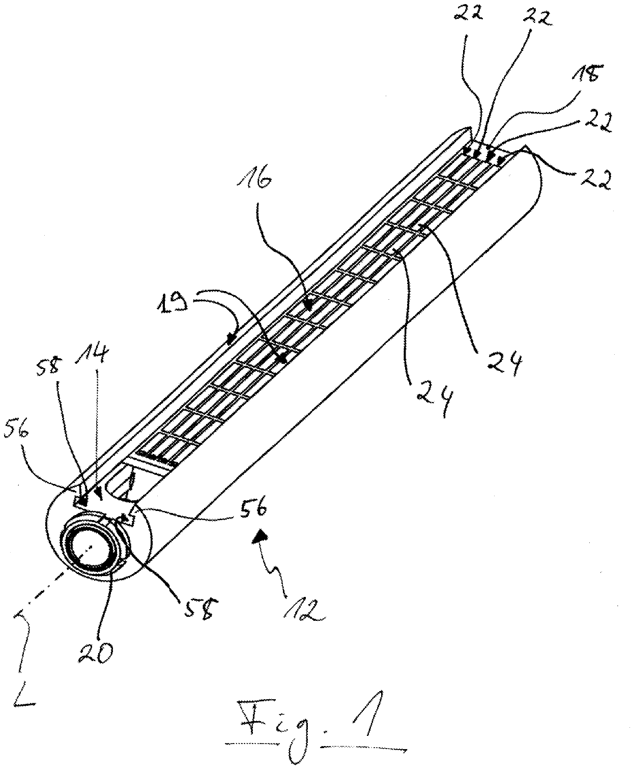
[0078]FIG. 1 shows a support rod 12 for holding an accessory component relative to a motion picture camera in a variable position along a longitudinal axis L of the support rod 12, wherein the support rod 12 has an outwardly open recess 14, and wherein the support rod 12 has a set back contact region 16 in the recess 14 that is accessible from the outside for the electrical contacting of the accessory component as will be explained more exactly in the following.

[0079]A contact board 18 is arranged in the recess 14, with the contact region 16 being formed at the upper side of the contact board 18 accessible from the outside. Four contact tracks 22 extend in parallel with the longitudinal axis L on the upper side of the contact board 18 that are arranged adjacent to one another and that are divided into contact sections 24 in a regular pattern along the longitudinal axis L. Both the ...


PUM


Abstract

A support rod for holding an accessory component relative to a motion picture camera in a variable position along a longitudinal axis of the support rod has at least one outwardly open recess. The support rod has a set back contact region in the recess that is accessible from the outside for the electrical contacting of the accessory component.

Description

RELATED APPLICATIONS[0001]This application is a continuation of U.S. patent application Ser. No. 16 / 111,367, filed Aug. 24, 2018, which claims priority to German Patent Application No. 102017119532.7, filed Aug. 25, 2017, the contents of which are incorporated herein by reference in their entirety.SUMMARY OF THE INVENTION[0002]The present invention relates to a support rod for holding an accessory component relative to a motion picture camera in a variable position along a longitudinal axis of the support rod. The accessory component can, for example, be fixedly fastened to the support rod by means of a clamping device. The position of the accessory component along the longitudinal axis of the support rod can be fixed here such that the accessory component can act in a desired manner and can in particular cooperate with the motion picture camera. The support rod can e.g. be integrated pair-wise into a support system of the motion picture camera, with a plurality of accessory compone...

Claims


Application Information

Patent Timeline
IPC IPC(8): G03B17/56G03B17/12G03B19/18
CPCG03B17/561G03B17/12G03B17/563G03B2217/002G03B19/18G03B2217/007G03B17/56F16M11/04G01R33/07G01V3/08H01R41/00
Inventor HAUBMANN, MICHAELTSCHIDA, CHRISTIAN
Owner ARNOLD & RICHTER CINE TECHN & BETRIEBS
Why Eureka
Try Eureka