

Automotive alternator rotor
a technology for alternators and auxiliary machines, applied in the direction of windings, magnetic circuit rotating parts, magnetic circuit shapes/forms/construction, etc., can solve the problems of automotive alternators, which are auxiliary machines, and have come to be considered a problem, and achieve the effect of quietness and assemblability
- Summary
- Abstract
- Description
- Claims
- Application Information
AI Technical Summary
Benefits of technology
Problems solved by technology
Method used
Image

Examples
embodiment 1
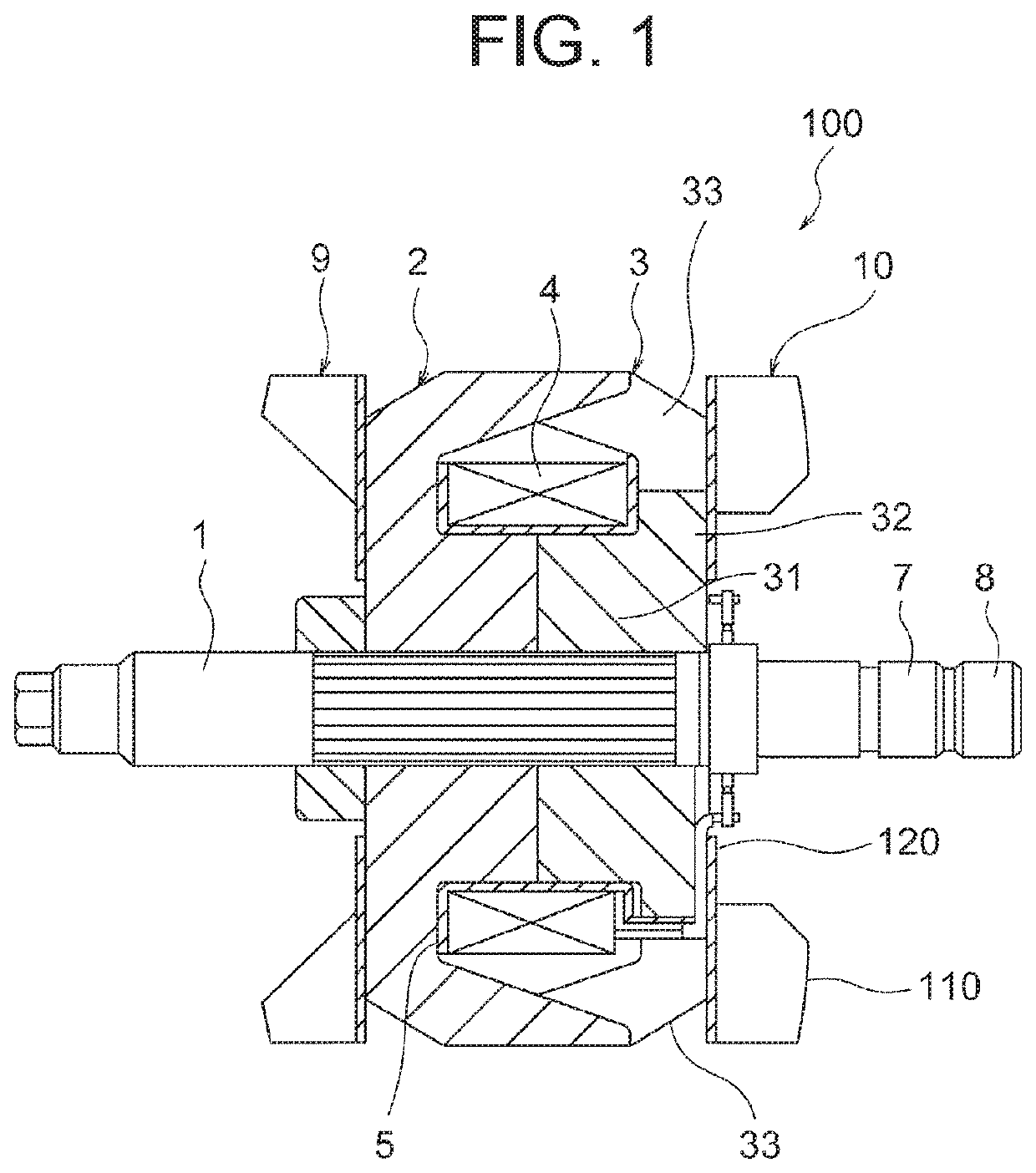
[0016]FIG. 1 is a cross section that is taken along a shaft axis of an automotive alternator rotor according to Embodiment 1 of the present invention. In the figure, a rotor 100 is rotatably supported in a frame of an automotive alternator (not shown), and is driven to rotate by an engine that is mounted to a vehicle. The rotor 100 has: a rotating shaft 1; first and second Lundell magnetic pole cores 2 and 3; a field coil 4; a resin bobbin 5; and first and second cooling fans 9 and 10.
[0017]The first and second magnetic pole cores 2 and 3 are fixed to the rotating shaft 1, and rotate together with the rotating shaft 1. The field coil 4 is wound onto the first and second magnetic pole cores 2 and 3 so as to have the resin bobbin 5 interposed. The first cooling fan 9 is fixed to an axial end surface of the first magnetic pole core 2 that is positioned at a front end. The second cooling fan 10 is fixed to an axial end surface of the second magnetic pole core 3 that is positioned at a r...
PUM
 Abstract
Description
Claims
Application Information