Handle Mechanism, Delivery System and Operation Method

Active Publication Date: 2021-09-30
MICRO TECH (NANJING) CO LTD +1
View PDF0 Cites 0 Cited by
  • Summary
  • Abstract
  • Description
  • Claims
  • Application Information

AI Technical Summary

Benefits of technology

The present invention provides a handle mechanism and a delivery system for tissue anchors. The handle mechanism comprises a body with first and second anchor delivery devices for controlling two tissue anchors, a cinching device for tightening the anchors, and a locking and cutting device for releasing the inner tubular member and a portion of the suture member. The delivery system comprises the handle mechanism and an endoscope. The invention allows for easier and more effective delivery of tissue anchors and sutures to a target tissue, with improved tightening and release mechanisms.

Problems solved by technology

Clipping devices are limited by a fixed distance and relationship between the prongs.
The fixed distance between the prongs limits the operator's ability to close defects that exceed this distance, which limits applicability to small defects.
The fixed relationship between the prongs limits the operator's ability to position the clip appropriately in relation to the area in need of treatment.
For instance, the clip may not be able to close a defect that is approached tangentially at a curve or angle.
Further, because the proximal ends of the legs are joined, the operator may not be able to adjust the positioning of prong of one clip without affecting the positioning of the prong of the second clip.
Positioning also may be limited because the clip may not be properly oriented when it is deployed or the clip may slip out of alignment during application.
If unequal pressure is applied to the legs during anchoring, closure may be sub-therapeutic and scissoring of the legs may occur that can result in tissue damage.
Presently used clips are only capable of capturing the mucosa and do not penetrate into the deeper wall layers (submucosa and muscular propria layers).
This device is capable of full-thickness (entire bowel wall) tissue capture and the closure of larger defects, however, the device cannot be delivered through the working (operative) channel of the endoscope and must be pre-mounted on the end of the endoscope.
It also involves multiple time consuming, technically demanding maneuvers and manipulations.
The size of the defect that can be closed is small, which limited by the diameter of the cap attachment.

Method used


Image

  • Handle Mechanism, Delivery System and Operation Method
  • Handle Mechanism, Delivery System and Operation Method
  • Handle Mechanism, Delivery System and Operation Method

Examples


Embodiment Construction

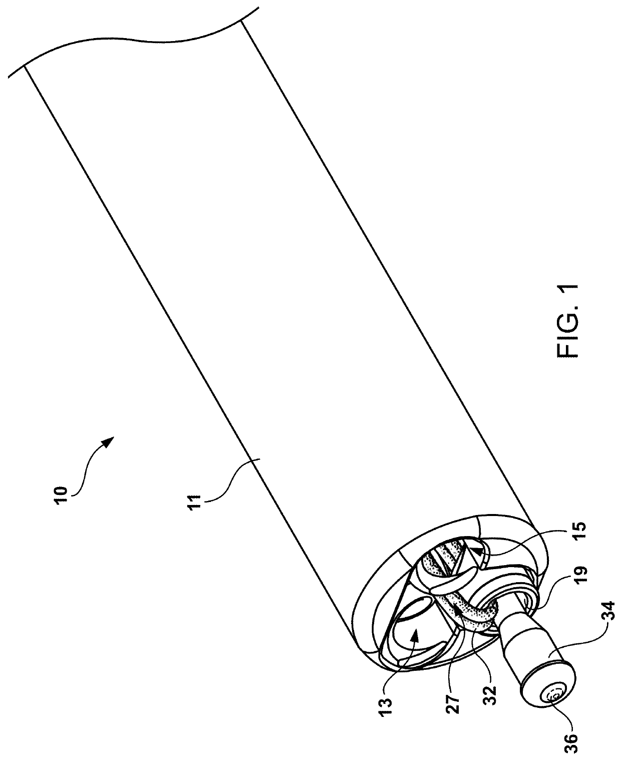
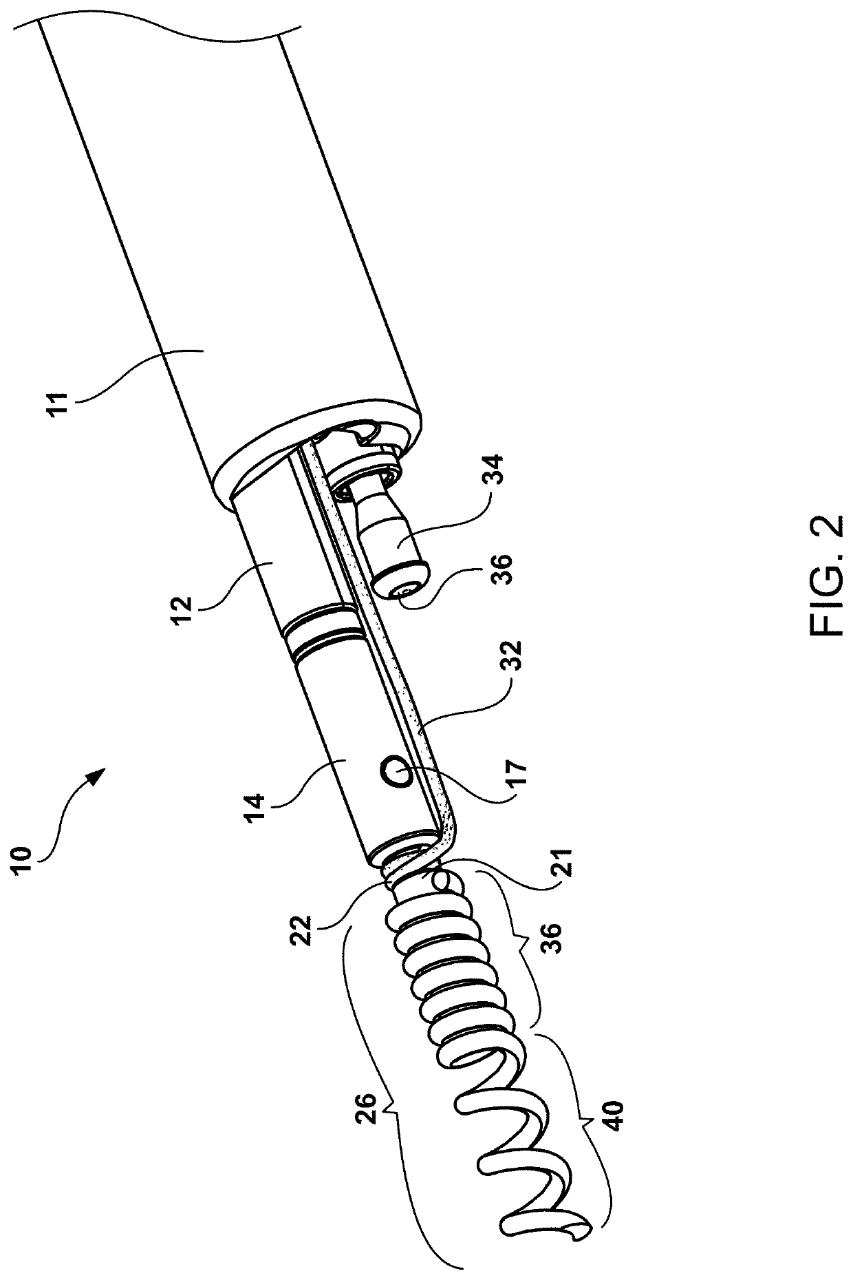
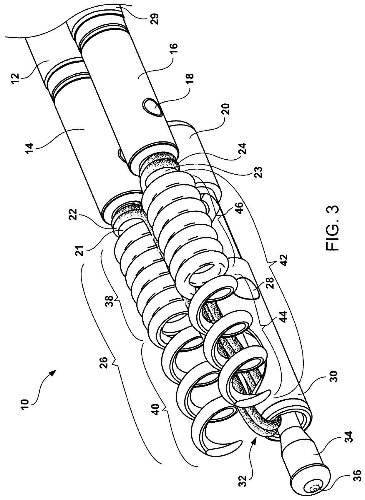
[0041]The present disclosure comprises a novel delivery system for delivering two or more helical anchors through an endoscope or colonoscope to repair a wall defect, achieve plication of tissue, or treat a lesion. The delivery system comprises an outer sheath tubular member designed to pass through the working channel of an endoscope.

[0042]Axially in parallel contained within the outer sheath tubular member are three individual inner tubular members, a first inner tubular member being designed to deploy a first helical tissue anchor (sometimes referred to as the “first helical device” hereinafter), a second inner tubular member being designed to deploy a second helical tissue anchor (sometimes referred to as the “second helical device” hereinafter), and a third inner tubular member containing a retraction member. The first inner tubular member coaxially contains a first reinforced tubular member that has a control wire allowing rotational manipulation of the first helical tissue an...


PUM


Abstract

Disclosed is a handle mechanism, including: a body, a first anchor delivery device provided to the body, a second anchor delivery device provided to the body, a tightening device provided to the body, and a locking and cutting device provided to the body. The first anchor delivery device is configured to control a first tissue anchor. The second anchor delivery device is configured to control a second tissue anchor. The tightening device is configured to pull a suture member.

Description

CROSS-REFERENCE TO RELATED APPLICATIONS[0001]This application is a continuation-in-part application of U.S. patent application Ser. No. 16 / 832,131 filed on Mar. 27, 2020, this U.S. Patent Application is a divisional application of U.S. patent application Ser. No. 15 / 661,613 filed on Jul. 27, 2017, which claims priority to U.S. Provisional Patent Application Ser. No. 62 / 367,592 filed on Jul. 27, 2016, which is incorporated herein by reference in its entirety.TECHNICAL FIELD[0002]The present disclosure relates to the field of medical devices, and in particular to a handle mechanism, a delivery system, and an operation method.BACKGROUND ART[0003]During a gastrointestinal endoscopy and treatment procedure, the operator often desires to repair or reconstruct a tear or defect, or otherwise approximate or fix tissue or other material by suturing.[0004]Metallic clipping devices were first introduced for the primary purpose of achieving hemostasis of focal gastrointestinal bleeding. Indicati...

Claims


Application Information

Patent Timeline
IPC IPC(8): A61B17/04
CPCA61B17/0401A61B17/0467A61B2017/00389A61B2017/0409A61B17/0469A61B2017/0034A61B2017/00818A61B2017/0441A61B2017/0464A61B2017/00407A61B17/0487A61B2017/0488A61B2017/0496A61B2017/00004A61B2017/00296
Inventor BINMOELLER, KENNETH F.HONGYAN, JINYUREK, MATTHEW THOMASHARTSFIELD, MICHAELGREELIS, JOHN
Owner MICRO TECH (NANJING) CO LTD
Why Eureka
Try Eureka