
Helically winding apparatus and method in a production line for manufacturing a non-metallic armature

a production line and helically winding technology, applied in the direction of continuous wounding machines, transportation and packaging, other domestic articles, etc., can solve the problems of reducing the quality of the produced articles, increasing the difficulty of technology, and low production efficiency, so as to increase the production capacity of the helically winding apparatus, reduce the rejection rate, and increase the production efficiency

Inactive Publication Date: 2021-10-07
LLC INNOTECH
View PDF4 Cites 0 Cited by
  • Summary
  • Abstract
  • Description
  • Claims
  • Application Information

AI Technical Summary

Benefits of technology

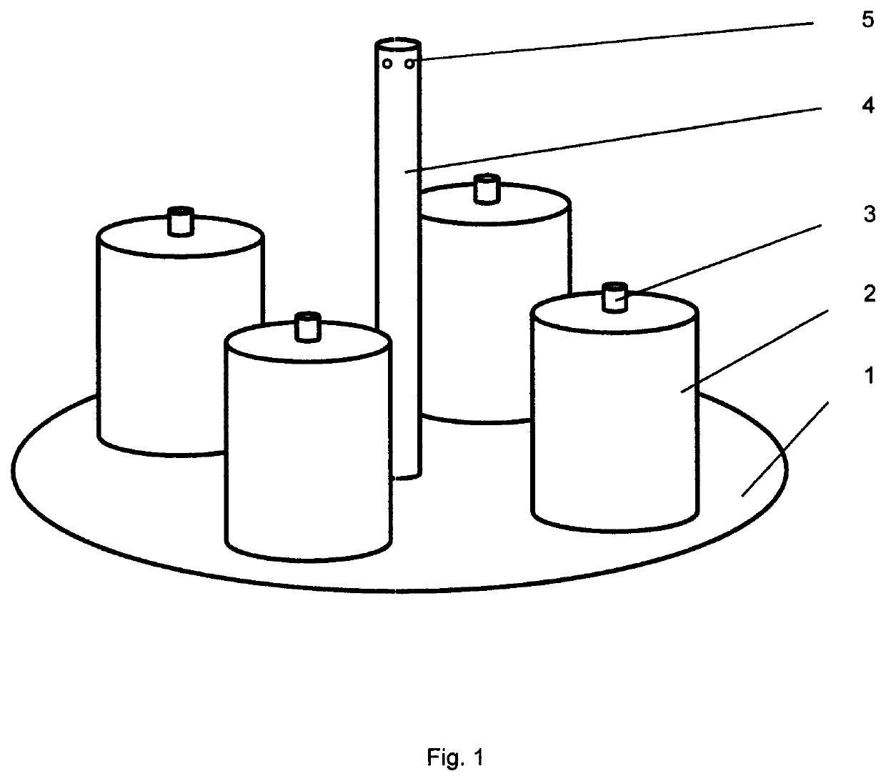
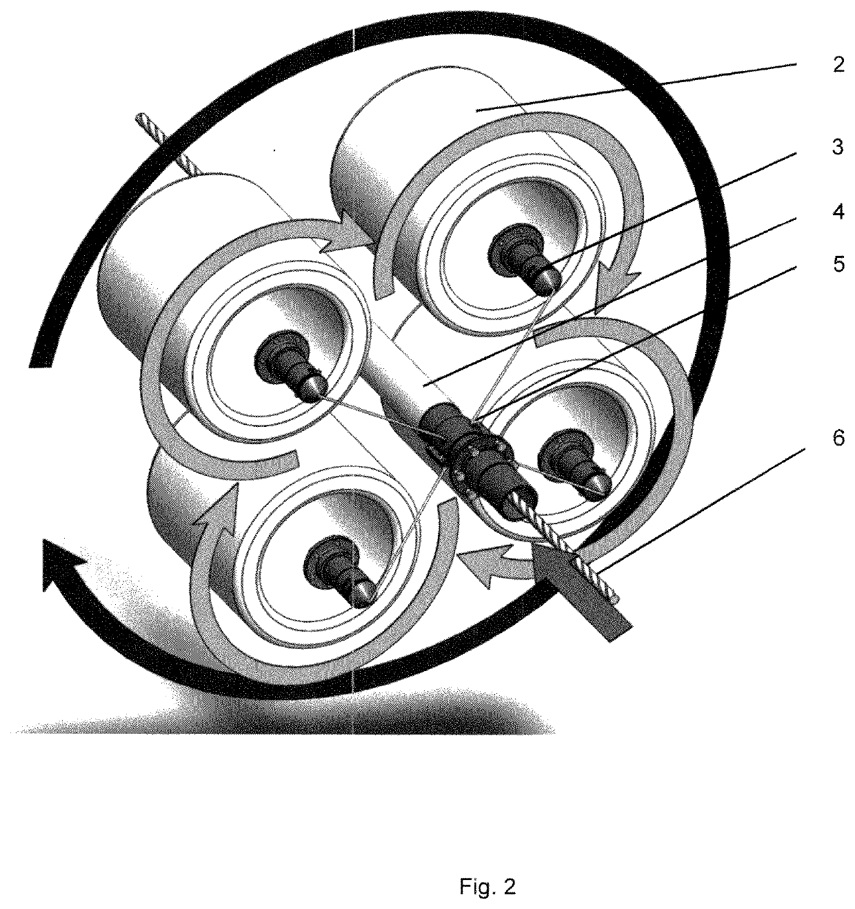
The invention uses internally unwound industrial roving bobbins instead of sheaves or externally unwound bobbins, which improves the productivity and reduces the rejection rate of the helically winding apparatus. Furthermore, twisting two or more roving threads before winding about the reinforcement rod eliminates the need for sequential installation of several helically winding apparatuses in the production line.

Problems solved by technology

A disadvantage of such helically winding apparatuses is low produceability.
Manufacturing of externally unwound roving bobbins having greater volume will not provide uniform supply of a thread when manufacturing a composite armature, so that a thread breakage or a nonuniform winding of the rod may be caused, thereby significantly reducing a quality of the produced articles.
Another disadvantage of the technical decision of RU 82247 is low produceability due to sequential mounting of several helically winding apparatuses for forming a winding of the composite armature rod, wherein it makes the technology more difficult and may require more frequent stops of the production line.

Method used


Image

  • Helically winding apparatus and method in a production line for manufacturing a non-metallic armature
  • Helically winding apparatus and method in a production line for manufacturing a non-metallic armature

Examples


Embodiment Construction

[0031]A technology of producing a composite armature is generally well-known for one skilled in the art and, thus, each step of the technology will not be described in details. The technology is based on the «pultrusion»—forming of elongated molded parts due to continuous extending of reinforcing material impregnated with an adhesive, through a heated forming die.

[0032]It is to note that the production line may include the following sequentially arranged components: a rack with roving bobbins; an aligning device; an impregnating bath with a tensioning device; a moulding assembly with a thread squeezing assembly; a winding assembly; a polymerization chamber; a cooling assembly; a pulling device; and an armature cord unwinding and cutting unit.

[0033]A rack with roving bobbins may be formed, for example, as a row of shelfs where rods are arranged to mount roving bobbins and to allow unwinding of the roving bobbins, for example, by rotation thereof about an axis of the rods.

[0034]The ro...


PUM

PropertyMeasurementUnit
lengthaaaaaaaaaa
temperatureaaaaaaaaaa
lengthaaaaaaaaaa

Abstract

The present invention generally relates to manufacturing of a composite armature, more particularly, to apparatuses for helically winding of a winding roving about a rod when manufacturing a composite armature. There is provided is a helically winding apparatus allowing use of internally unwound roving bobbins instead of sheaves. The helically winding apparatus for a composite armature production line, the apparatus comprising: a disk-shaped creel (1) rotatable about its axis, wherein at least two drums (2) designed to have internally unwound direct roving bobbins mounted therein are mounted on a base of the disk-shaped creel, and each drum is configured to rotate about its axis and to unwind direct roving threads from a bobbin inner side, wherein each drum for placing bobbins of the direct roving is provided with a thread tensioner (3) placed thereon to provide twisting of the direct roving thread relative to its axis when the drum is rotated about its axis to form a twisted roving, wherein the helically winding apparatus further comprises: a cylindrical sleeve (4) positioned in a center of the disk-shaped creel and configured to pass a reinforcement rod through a center of the cylindrical sleeve, wherein the cylindrical sleeve has holes (5) for passing the twisted roving therethrough and helically winding of the twisted roving about the reinforcement rod when the disk-shaped creel is rotated about its axis. A technical effect provided by the claimed invention is an increased produceability of the helically winding apparatus, increased productivity, and a reduced rejection rate.

Description

BACKGROUND OF THE INVENTION[0001]The present invention generally relates to manufacturing of a non-metallic composite armature, more particularly, to apparatuses for helically winding of a winding roving about a rod when manufacturing the composite armature. There is provided a helically winding apparatus allowing use of internally unwound roving bobbins instead of sheaves.DESCRIPTION OF RELATED ART[0002]Known in the art are production lines for manufacturing a non-metallic composite armature, the production lines including the following sequentially arranged components: a rack with roving bobbins; an aligning device; an impregnating bath with a tensioning device; a moulding assembly comprising a thread squeezing assembly; a winding assembly formed as a helically winding apparatus; a polymerization chamber; a cooling assembly; a pulling device; and an armature cord unwinding and cutting unit. The helically winding apparatus is intended to wind a winding roving about a rod of the com...

Claims


Application Information

Patent Timeline
Patent Type & Authority Applications(United States)
IPC IPC(8): B29C70/38B29C70/86D01H1/18B65H54/14B29C70/52
CPCB29C70/384B29C70/86D01H1/18B29L2023/22B29C70/523B65H2701/31B65H54/14B29C70/52B65H49/18B29C53/581B65H2701/314B65H81/06E04C5/07
Inventor ARKHIPOV, EVGENY PAVLOVICHPAVLICHENKOV, MIKHAIL ALEKSEEVICHDOYKHEN, DMITRY YURYEVICHSHTERENLIKHT, VADIM DAVIDOVICH
Owner LLC INNOTECH
Learn More