This helps you quickly interpret patents by identifying the three key elements:
Problems solved by technology
Method used
Benefits of technology
Benefits of technology
The objective of this patent is to create a seat air conditioner that can improve comfort for both the front and rear seat spaces, while also reducing energy consumption for cooling the vehicle interior.
Problems solved by technology
Therefore, cold air generated by the vehicle air conditioner disposed in the instrument panel of the vehicle and blown out into the front seat space is entangled by the blown air and is blown into the rear seat space.
Method used
Image
Click on the blue label to locate the original text in one second.
Reading with bidirectional positioning of images and text.
Examples
first embodiment
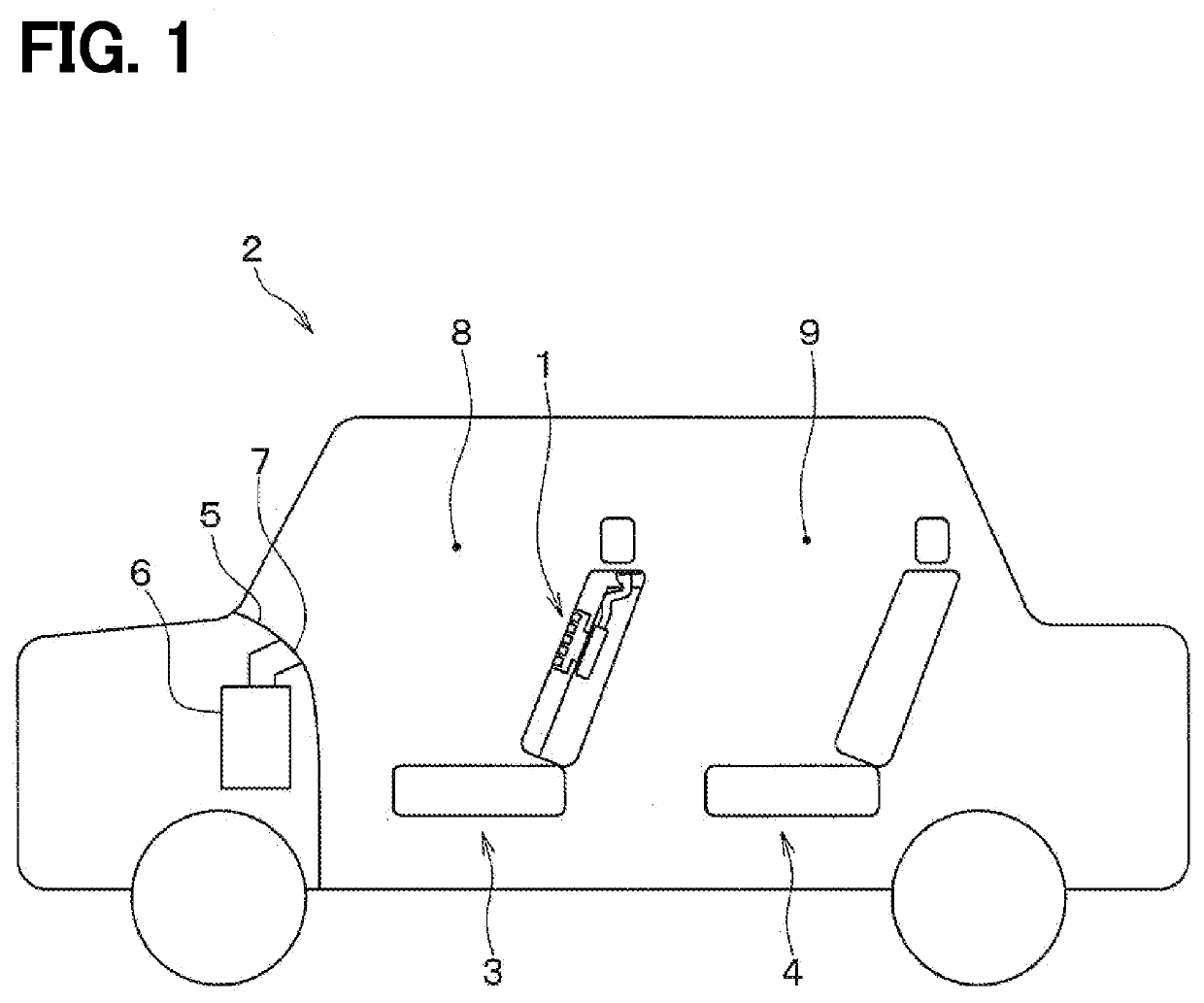
[0029]A first embodiment will be described with reference to the drawings. As shown in FIG. 1, the vehicle 2 in which a seat air conditioner 1 of the present embodiment is mounted has two seat rows with front seats 3 and rear seats 4. The seat air conditioner 1 of the present embodiment is disposed in the front seat 3. Alternatively, the seat air conditioner 1 may be disposed in both the driver seat and the passenger seat of the front seats 3 or may be disposed in either one of them. In the following description, the front seat 3 may be referred to as a “seat,” and the rear seat 4 may be referred to as a rear seat.
[0030]A vehicular air conditioner 1 for air-conditioning a vehicle interior is disposed inside an instrument panel 5 of the vehicle 2. The vehicle air conditioner 6 draws air outside of the vehicle interior or air inside of the vehicle and blows out conditioning air having an adjusted temperature and humidity into the vehicle interior through an air outlet 7 formed on the ...
second embodiment
Modification to the Second Embodiment
[0067]In the above description of the second embodiment, the guide member 50 has the angles θ1 and θ2 at the second position within the range of 45°=θ2>=−135°, respectively. However, the rages of the angles θ1 and θ2 are not necessarily limited to this range. For example, in a modification to the second embodiment, the guide member 50 at the second position is configured to have the angles θ1 and θ2 within the range of 60°=θ2>=−120°, respectively. Further, it is more preferable that the guide member 50 at the second position is configured to have the angles θ1 and θ2 that are substantially perpendicular to the seat upper surface 18. By setting the angles in this way, it is possible to cause an angle of a mainstream of the blown air that forms the air curtain to be perpendicular to the seat upper surface 18. As a result, it is possible to enhance the function of the air curtain as an air wall that separates the front seat space 8 from the rear sea...
third embodiment
[0068]A third embodiment will be described below. In the third embodiment, an operating way of the guide member 40 is changed from the first embodiment, and the other parts are similar to that in the first embodiment, so only the difference from the first embodiment will be described.
[0069]FIG. 11 is a block diagram showing a control system of the seat air conditioner 1 according to the third embodiment. In the third embodiment, the guide member 50 is configured to be rotated by an electric motor 60 for driving the guide member.
[0070]The vehicle 2 with the seat air conditioner 1 according to the third embodiment includes a detector 70 for detecting an occupant on the rear seat 4. As an example of the detector 70, a courtesy switch that detects opening / closing of the rear door, a seat sensor disposed in the rear seat 4, an in-vehicle camera, and the like, may be used. The signal from the detector 70 is transmitted to a controller (ECU: Electronic Control Unit) 80.
[0071]The controller...
PUM
Abstract
A seat air conditioner includes an air passage that is disposed in a seat of the vehicle, a blower that blows air into the air passage, an outlet through which the air flowing through the air passage is blown as a blown air toward a rear side of a vehicle interior along an upper surface of the seat, and a guide member that is disposed behind the outlet to be moveable between a first position and a second position. The guide member allows the blown air from the outlet to flow toward the rear side of the vehicle interior together with a surrounding air entangled by the blown air when the guide member is at the first position and guides the blown air from the outlet toward a ceiling side or a floor side of the vehicle interior when the guide member is at the second position. The guide member is retracted into a housing space defined in the seat when the guide member is at the first position. At least a portion of the guide member protrudes upward from the upper surface of the seat when the guide member is at the second position.
Description
CROSS REFERENCE TO RELATED APPLICATIONS[0001]This application is a continuation application of International Patent Application No. PCT / JP2019 / 044715 filed on Nov. 14, 2019, which designated the U.S. and claims the benefit of priority from Japanese Patent Application No. 2018-237458 filed on Dec. 19, 2018. The entire disclosure of all of the above application is incorporated herein by reference.TECHNICAL FIELD[0002]The present disclosure relates to a seat air conditioner disposed in a seat of a vehicle.BACKGROUND ART[0003]Various types of seat air conditioners mounted in a vehicle seat have been known. Such a conditioner is provided in a front seat of a vehicle, and air drawn from the back portion of the seat surface of the front seat is blown out toward the rear space in the vehicle interior through an outlet formed on a side surface of the front seat, for example. When the air is blown out from the outlet on the side surface of the front seat, air around the blown air (hereinafter...
Claims
Application Information
Patent Timeline
Application Date:The date an application was filed.
Publication Date:The date a patent or application was officially published.
First Publication Date:The earliest publication date of a patent with the same application number.
Issue Date:Publication date of the patent grant document.
PCT Entry Date:The Entry date of PCT National Phase.
Estimated Expiry Date:The statutory expiry date of a patent right according to the Patent Law, and it is the longest term of protection that the patent right can achieve without the termination of the patent right due to other reasons(Term extension factor has been taken into account ).
Invalid Date:Actual expiry date is based on effective date or publication date of legal transaction data of invalid patent.

