Vehicle occupant restraint system
a technology for occupants and restraints, applied in the field of vehicle occupant restraint systems, can solve the problems of increasing the tension of webbing before acceleration is applied to the vehicle, and achieve the effects of reducing cost, improving comfort and occupant protection performan
- Summary
- Abstract
- Description
- Claims
- Application Information
AI Technical Summary
Benefits of technology
Problems solved by technology
Method used
Image
Examples
first embodiment
Operation and Effects of First Embodiment
[0068]Next, the operation and effects of the present embodiment will be described.
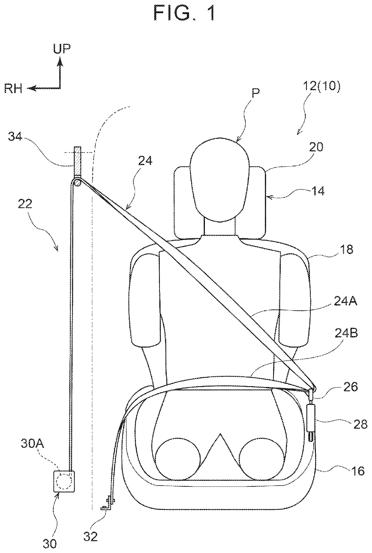
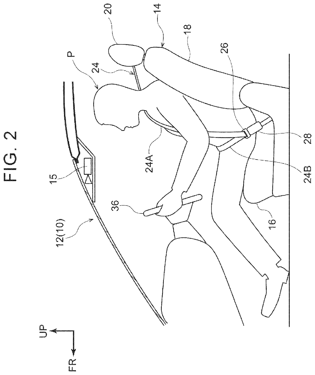
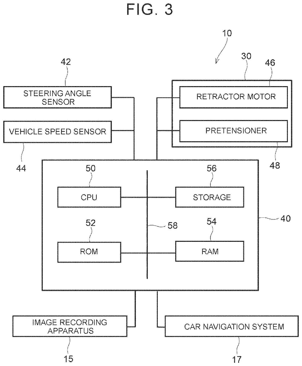
[0069]In the vehicle occupant restraint system 10 of the present embodiment, as shown in FIG. 1 and FIG. 3, the retractor 30 of the seatbelt device 22 includes the retractor motor 46. When the retractor motor 46 is driven, the spool 30A rotates in the take-up direction, and the webbing 24 is taken up. Thus, when a high acceleration is input to the vehicle 12, the inertial movement of the occupant P is reduced by increasing the tension of the webbing 24.
[0070]The vehicle occupant restraint system 10 includes the road surface condition detection unit 64 that detects a road surface condition ahead of the vehicle 12 in the direction of travel, the vehicle speed determination unit 60 and steering angle velocity determination unit 62 that detect the status of the vehicle 12, and the ECU 40 that drives the retractor motor 46. The CPU 50 of the ECU 40 computes an estima...
second embodiment
Operation and Effects of Second Embodiment
[0084]Next, the operation and effects of the present embodiment will be described.
[0085]The above configuration is similar to the configuration of the vehicle occupant restraint system 10 of the first embodiment except that the seatbelt device 72 includes the emergency lock mechanism 74, so similar effects to those of the first embodiment are obtained. The seatbelt device 72 includes the emergency lock mechanism 74, and the emergency lock mechanism 74 restricts pulling out of the webbing 24 after the webbing 24 is taken up by the predetermined amount by the CPU 50. Therefore, the output of the retractor motor 46 does not need to be increased to hold a state after the webbing 24 is taken up.
[0086]The seatbelt device 72 includes the emergency lock mechanism 74 that stops the rotation of the spool 30A when the spool 30A rotates at the predetermined rotation speed or higher. The emergency lock mechanism 74 is an ELR generally adopted to a seatbe...
third embodiment
Operation and Effects of Third Embodiment
[0097]Next, the operation and effects of the third embodiment will be described.
[0098]With the above configuration as well, since the configuration is similar to that of the vehicle occupant restraint system 10 of the first embodiment except that taking up of the webbing 24 and canceling taking up are allowed by operating the drive mode select switch 94 connected to the ECU 92, similar effects to those of the first embodiment are obtained. Taking up of the webbing 24 by the predetermined amount or canceling taking up are performed by operating the drive mode select switch 94 connected to the ECU 92, so the occupant P is restrained or restraining is canceled at occupant's required timing.
[0099]Since the status of operation of the drive mode select switch 94 is determined, the webbing 24 is taken up at the time when drive modes in which an acceleration is easily applied to the vehicle 12, such as the rough road drive mode and the sport drive mo...
PUM
 Abstract
Description
Claims
Application Information
 - R&D
- Intellectual Property
- Life Sciences
- Materials
- Tech Scout
- Unparalleled Data Quality
- Higher Quality Content
- 60% Fewer Hallucinations
Browse by: Latest US Patents, China's latest patents, Technical Efficacy Thesaurus, Application Domain, Technology Topic, Popular Technical Reports.
© 2025 PatSnap. All rights reserved.Legal|Privacy policy|Modern Slavery Act Transparency Statement|Sitemap|About US| Contact US: help@patsnap.com


