Wireless camera system

Active Publication Date: 2021-10-07
R F WIRELESS SYST INC
View PDF0 Cites 0 Cited by
  • Summary
  • Abstract
  • Description
  • Claims
  • Application Information

AI Technical Summary

Benefits of technology

The present invention aims to provide a system for controlling a wireless remote camera system without interrupting the video signal feed. This allows for real-time adjustment of camera settings while transmitting images. Additionally, the system should not cause significant workflow issues and be lightweight.

Problems solved by technology

In prior art wearable / mountable camera solutions, the video engineer in the broadcast facility did not have real time control of the video setting of the wearable / mountable camera at the board level.
This is a significant workflow issue for live use of this resource.
Other problems include the capacity of the battery powering the wearable / mountable camera was not maximized to meet the needs of a typical live event; such as a hockey, baseball, football game of roughly 3 to 4 hours.
This required a battery change midway through an event, which interrupts the wearer's regular workflow.
While the DragonflyEncoder / Transmitter presently used in the industry as a solution for video transport from a wearable / mountable camera, it lacks various feature sets to control the camera connected to it.
For example:1. The Dragonfly™'s use of Marshall™'s on-Screen menu system for video control interrupts the production group's live use of this camera (which results in the camera not being adjustable while transmitting real time images);2. Local, short range Wi-Fi connection needed to achieve limited video control through browser based GUI, which does not provide the range, interface, or real-time control to use this camera in typical live event coverage;3. DragonflyTransmitter does not support an RCP (Remote Control Panel); and,4. Marshall™ wearable / mountable camera supports an RCP, but only in a wired (connected) configuration.
Developing a small lightweight system with sufficient battery life, and with full functionality was very difficult.
Further, it would be unacceptable in professional broadcast video transmission to interrupt the video signal feed from the remote camera in order to control the camera; however, it would readily be believed by those skilled in the art that it would be necessary to use sophisticated highly functional complicated circuit components such as microprocessors, UARTS, and so on, to develop a system for providing controls signals to a remote camera that meets the above-stated requirements, and that fully meets the objects set forth below, which objects are not met by the prior art.
Also, the issue of the need for the video signal from the remote camera to be uninterrupted in order to control the camera is not discussed.
The Jannard et al document discusses various capabilities of the overall system, but does not solve the issues of size and / or weight, battery life, and the need for the video signal from the remote camera to be uninterrupted in order to control the camera.
Further, the Jannard et al does not discuss the installation of the camera system on a helmet or even on a wearer's body.

Method used


Image

  • Wireless camera system
  • Wireless camera system
  • Wireless camera system

Examples


Embodiment Construction

[0048]Reference will now be made to FIGS. 1 through 16, which show an exemplary embodiment according to the present invention.

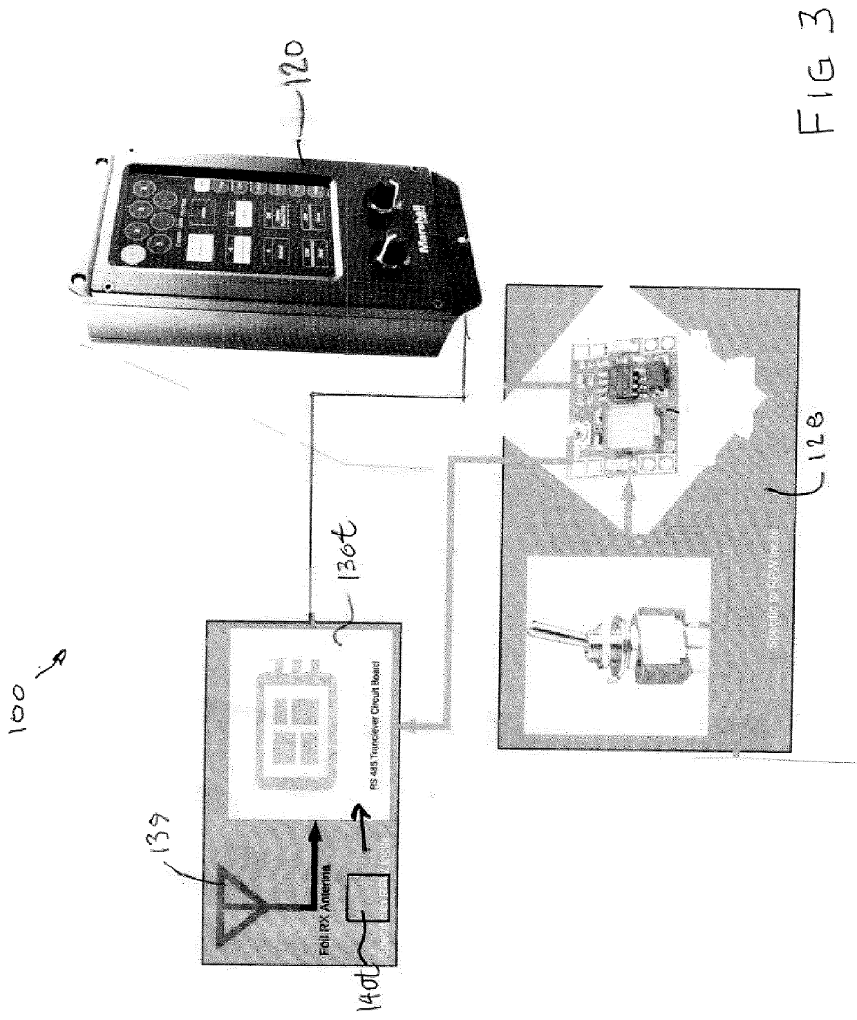
[0049]The applicant's solution to the aforementioned live event workflow issues is the InCite™ system for providing controls signals to a wireless remote camera, as indicated by the general reference numeral 100 in FIGS. 3 and 7. The camera control system 100 is for controlling various operating characteristics of the wireless video camera 110 mounted on a helmet 102. The wireless video camera 110 shown is a known device made and marketed by Marshall Electronics, Inc. of Torrance, Calif., USA, being preferably a Marshall™ Model V-1292B-2MP (59.94 / 29.97 fps)|V-1292-2MP (60 / 50 / 30 / 25 fps) 2.5MP Full-HD Color Board Camera).

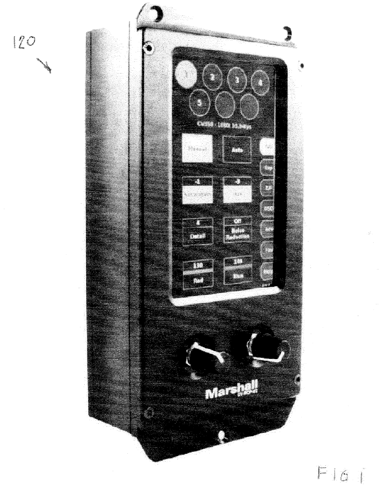
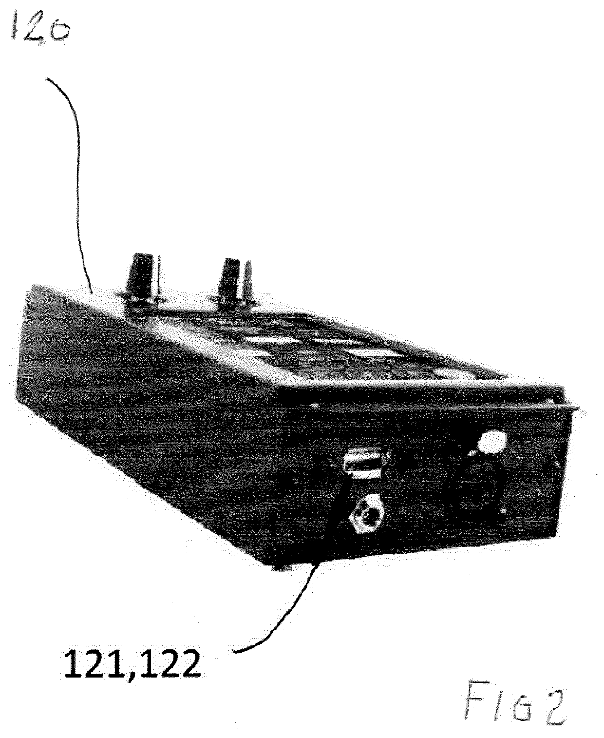
[0050]The camera 110 is controlled using a remote control panel (RCP) 120, such as, preferably, remote control panel model CV-RCP-V2 Multi-Camera Control Touchscreen RCP, which serves as a signal generating device also manufactured and marketed...


PUM


Abstract

A system for providing controls signals to a wireless remote camera comprises a signal generating device that presents forward and inverse polarity pulse trains. A transmitter data converter circuit has a forward polarity input point for receiving the inverse polarity pulse trains and an inverse polarity input point for receiving the forward polarity pulse trains, and converts the forward and inverse polarity pulse trains to a conditioned unitary pulse train. A modulator circuit modulates the conditioned unitary pulse train onto an RF carrier. A demodulator circuit demodulates the modulated output wave to produce a reproduction of the conditioned unitary pulse train. A receiver data converter circuit converts the conditioned unitary pulse train to conditioned forward polarity pulse trains and conditioned inverse polarity pulse trains. A camera control circuit produces control signals based on the conditioned forward and inverse polarity pulse trains. A wireless remote camera receives the control signals.

Description

FIELD OF THE INVENTION[0001]The present invention relates to the remote control of mobile video cameras, and more particularly to the wireless remote control of mobile remotely controlled video cameras.BACKGROUND AND SUMMARY OF THE INVENTION[0002]In many events such as sports, mobile remotely controlled video cameras are mounted on players, officials, participants, equipment used by players and / or officials and / or participants, and so on. These mobile remotely controlled video cameras are typically referred to as wearable / mountable cameras. In order for these wearable / mountable cameras to be used in live, line-cut broadcast workflow, the video engineer needs to have control of the image setting at all times. This is required so the video engineer can closely match the video image to the other broadcast cameras being used at the same live broadcast event.[0003]In prior art wearable / mountable camera solutions, the video engineer in the broadcast facility did not have real time control...

Claims


Application Information

Patent Timeline
IPC IPC(8): H04N5/232H04B1/40A42B3/04H04N5/225
CPCH04N5/23203H04B1/40H04N5/2253H04N5/2257A42B3/042H04W4/06H04N23/66H04B1/034H04B1/04H04B1/06H04N23/54H04N23/57
Inventor BUNN, ROBERT DOUGLASBORISS, BENJAMINGROHMANN, RALPHEADY-LAPSLEY, BROOKEEADY, LOCKE NIEL NORMANEADY, SHEA MARSHALL COLE
Owner R F WIRELESS SYST INC
Why Eureka
Try Eureka