
Patient Raiser

a raiser and patient technology, applied in the field of patient raisers, can solve the problems of caregivers not meeting the needs of those who can walk without assistance, caregivers can develop problems of their own, and the internal suture can be prone to rupture, so as to reduce the risk of pain and injury

Active Publication Date: 2021-10-14
NIKORA ANITA +1
View PDF0 Cites 3 Cited by
  • Summary
  • Abstract
  • Description
  • Claims
  • Application Information

AI Technical Summary

Benefits of technology

The invention is a device and method that allows a person to lie down or get up while reducing the risk of pain and injury. The device is controlled by the patient, so they can transfer between the two positions without assistance from a human caregiver. Additionally, there is a stabilizer that helps keep the device stable when the patient moves between the two positions.

Problems solved by technology

For example, a woman recovering from Caesarean section surgery may be fully capable of sitting, standing and walking, but may risk rupture of internal sutures should she attempt to lie down, or sit up, without assistance.
Such devices are therefore designed to carry the entire weight of a patient in transferring the patient to or from a bed to a wheelchair or similar mobility device, and do not meet the needs of those who can walk without assistance.
In giving such assistance, caregivers can develop problems of their own such as carpal tunnel syndrome, back pain and pinched nerves.
While the appliance reduces the physical strain on a support person to raise the patient to a sitting position, it nevertheless requires a support person, which may not always be available and may add to the overall expense of caring for the patient.
The disclosed device provides a number of disadvantages, including requiring a patient to be positioned on and strapped to the device before use (therefore necessitating use of a caregiver).
In addition, the device does not appear to be designed to enable a patient to transfer to and from a pre-existing bed.
Rather, it appears that the device takes the place of a bed, reducing comfort for the patient and the flexibility of the device.
While the device would assist certain patients to sit up or lie down, the device nevertheless requires a certain level of dexterity and strength on the part of the patient, and risks injury to patients suffering certain ailments.
The device would therefore not be suitable to assist all patients, particularly those suffering more severe ailments.

Method used


Image

  • Patient Raiser
  • Patient Raiser
  • Patient Raiser

Examples


Embodiment Construction

[0058]The invention is now further described as exemplified in the FIGURES.

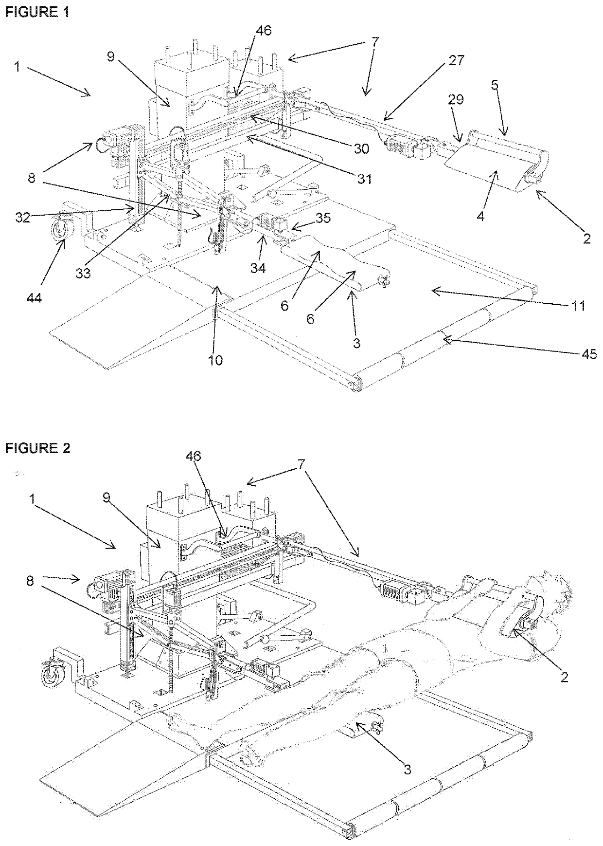
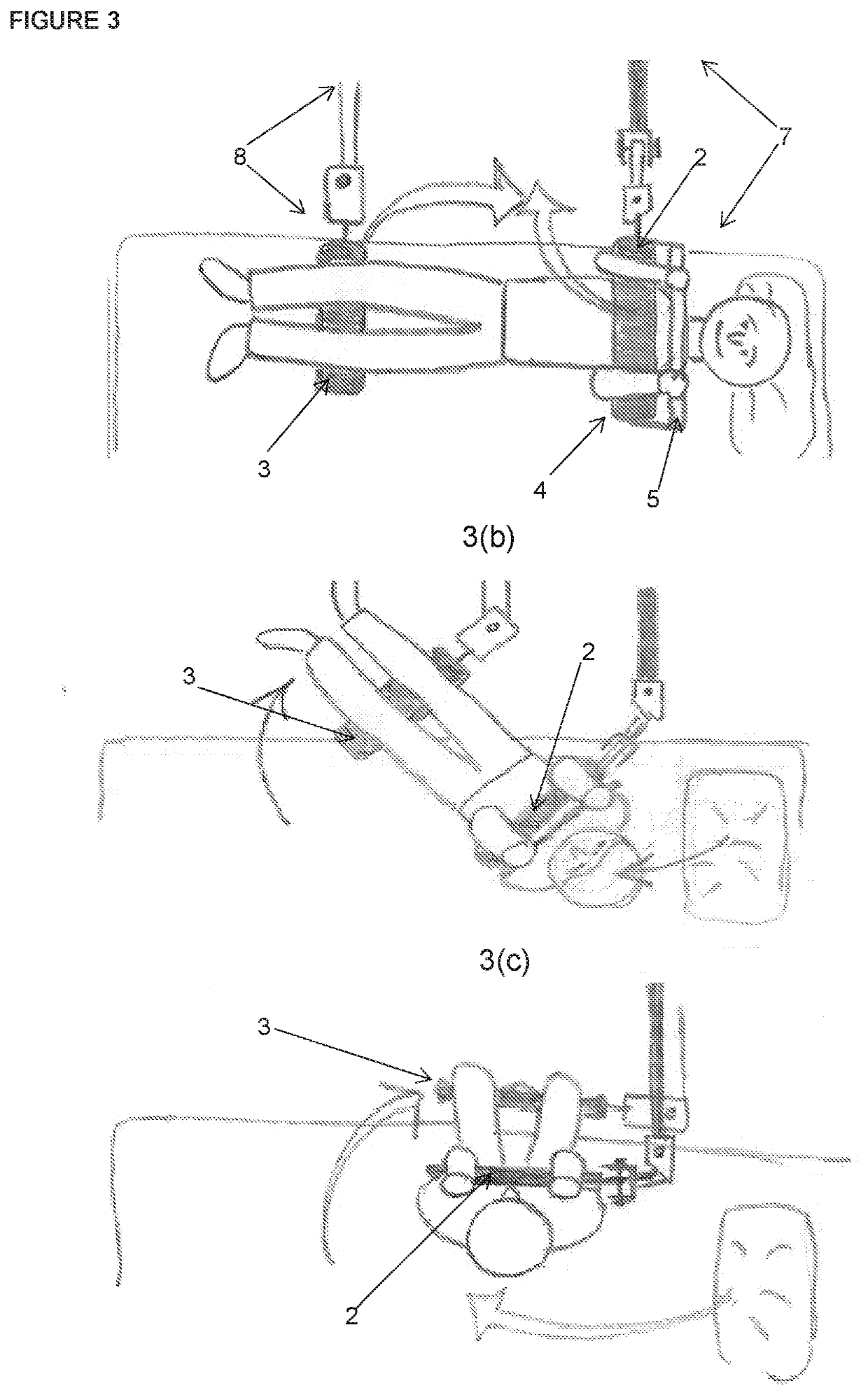
[0059]FIGS. 1 and 2 show a patient raiser device 1 comprising an arm hold 2 and a leg support 3. The arm hold further comprises a ‘cuddle pad’4, and a hand grip 5. In use a patient clinches the arm hold 2 to his or her chest has shown in FIG. 2. The leg support 3 comprises a panel incorporating recesses 6 to accommodate each leg of the patient as shown in FIG. 2.

[0060]In the embodiment shown the device comprises a leg support 3, which is an optional feature of the invention that may not be required where a person has sufficient strength to rotate on his or her buttocks to face a face of the bed once sitting up, or to face the end of the bed in preparation for lying down.

[0061]The arm hold 2 and the leg support 3 each connect to a centre post assembly 9 via an arm hold assembly 7 and a leg support assembly 8 respectively. To stabilise the device 1 against the weight of the patient, and prevent the device 1 fro...


PUM


Abstract

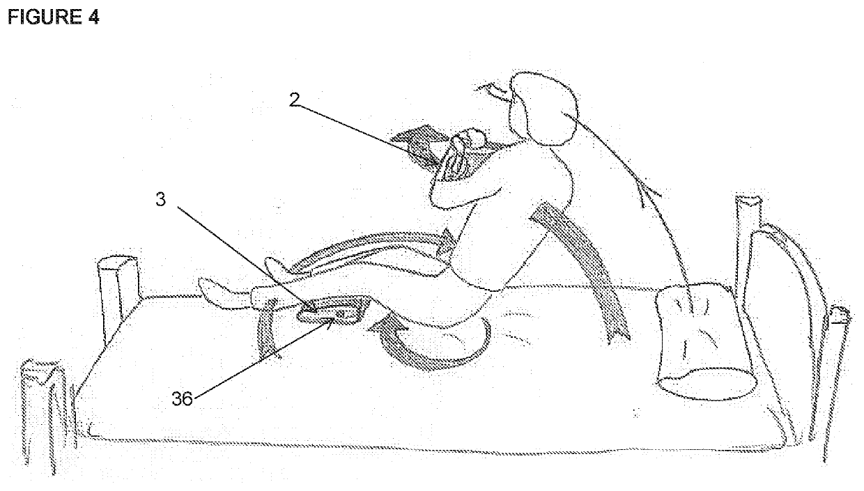
The application relates to a device for, and method of transferring a patient on a bed between a lying position along a bed to a seated position facing the side of a bed. The device comprises an arm hold to allow the patient to clinch the arm hold to his or her chest, thereby enabling the device to transfer the patient between a lying position and a seated position. Preferably, the device further comprises a leg support to assist in transferring the lower portion of the patients body between a lying position and a seated position.

Description

CROSS-REFERENCE TO RELATED APPLICATION(S)[0001]This Application is a Section 371 National Stage Application of International No. PCT / AU2019 / 051130, filed Oct. 17, 2019 and published as WO 2020 / 077408 A1 on Apr. 23, 2020, in English, and further claims priority to Australian Application Ser. No. 2018903955, filed Oct. 18, 2018.FIELD[0002]The present invention is generally directed to a device for, and method of, transferring a person on a bed from a lying position to a seated position, and vice versa.BACKGROUND OF THE INVENTION[0003]Many members of the community are self-sufficient when sitting, standing or walking, but require assistance transitioning from a lying position to a seated position, and vice versa. For example, a woman recovering from Caesarean section surgery may be fully capable of sitting, standing and walking, but may risk rupture of internal sutures should she attempt to lie down, or sit up, without assistance. Others who cannot without assistance lie down, or sit u...

Claims


Application Information

Patent Timeline
Patent Type & Authority Applications(United States)
IPC IPC(8): A61G7/053A61G7/10
CPCA61G7/053A61G7/1017A61G7/1044A61G2200/34A61G7/1092A61G2200/327A61G7/1096A61G7/1001A61G2203/70A61G2200/56A61G7/1063A61G7/1046A61G7/1019A61G7/1057A61G7/1059A61G7/1076A61G7/1086
Inventor NIKORA, ANITAJOHNSON, GARY
Owner NIKORA ANITA
Learn More