
Eureka
For R&D, Eureka makes reading and utilizing patents & technical documents easy.
Eureka AIR
Designed for self-driven R&D workflows. Generate viable solutions, solve complex R&D challenges, empower your innovation with AI.

Eureka Materials
Designed for material experts only. Revolutionize your material R&D, from search, analyze, to developing new materials.

TechResearch
Generate reliable direction feasibility study reports for your R&D in just a few steps.

TechSeek
Discover and master advanced knowledge NOW. Basics, ideas, possibilities, all at once.

TechMind
As an expert in R&D Theories, TechMind can generates customized viable solutions instantly.

TechRisk
Analyze your overall solution with one click, know your potential R&D risks in advance.

TechMonitor
Get weekly tech updates, stay abreast of the latest tech innovations and key insights.
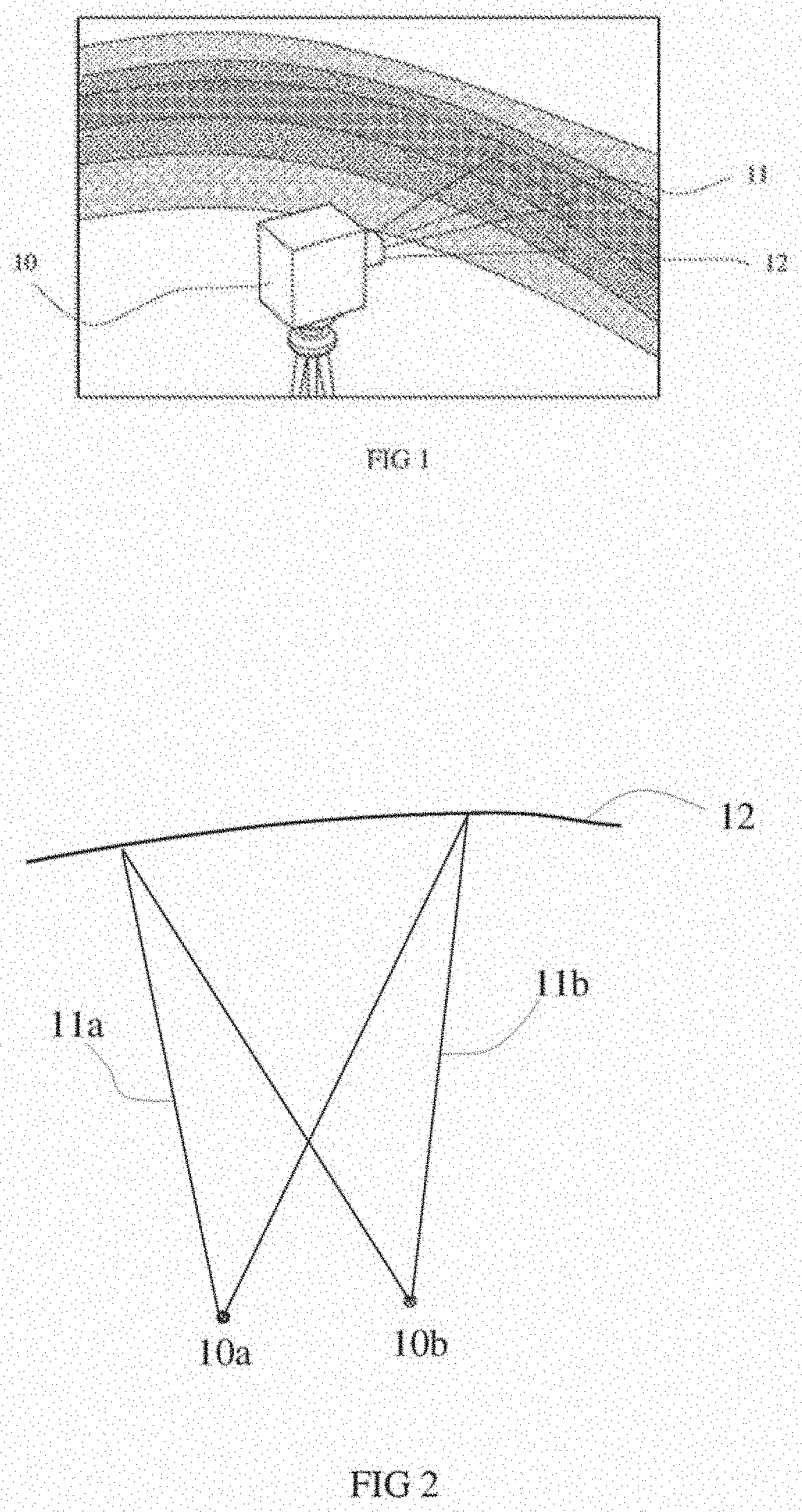
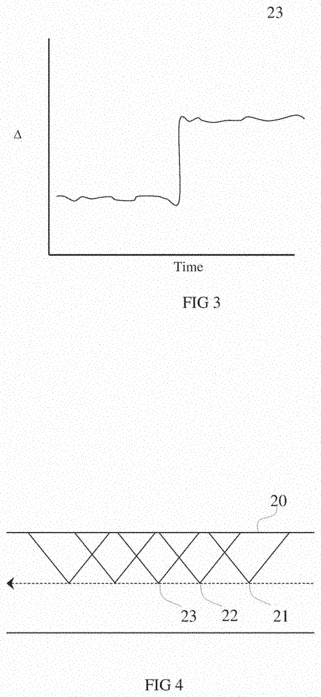
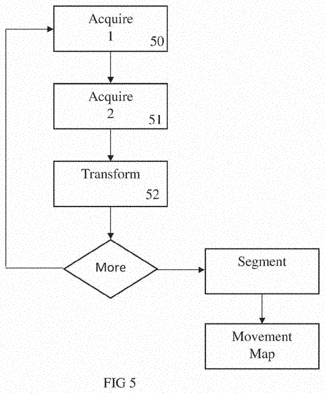
Wall visualisation from virtual point of view
- Summary
- Abstract
- Description
- Claims
- Application Information
AI Technical Summary
Benefits of technology
Problems solved by technology
Method used
Image

Examples
Embodiment Construction
[0034]Embodiments of the present invention reside primarily in a slope monitoring system comprising a slope monitoring device and a processor for transforming measured data to a virtual point of view. Accordingly, the elements of the device and the method steps of the processor have been illustrated in concise schematic form in the drawings, showing only those specific details that are necessary for understanding the embodiments of the present invention, but so as not to obscure the disclosure with excessive detail that will be readily apparent to those of ordinary skill in the art having the benefit of the present description.
[0035]In this specification, adjectives such as first and second, left and right, and the like may be used solely to distinguish one element or action from another element or action without necessarily requiring or implying any actual such relationship or order. Words such as “comprises” or “includes” are intended to define a non-exclusive inclusion, such that...
PUM
 Abstract
Description
Claims
Application Information
 - R&D Engineer
- R&D Manager
- IP Professional
- Industry Leading Data Capabilities
- Powerful AI technology
- Patent DNA Extraction
Browse by: Latest US Patents, China's latest patents, Technical Efficacy Thesaurus, Application Domain, Technology Topic, Popular Technical Reports.
© 2024 PatSnap. All rights reserved.Legal|Privacy policy|Modern Slavery Act Transparency Statement|Sitemap|About US| Contact US: help@patsnap.com