Sprinkler Head Accessory

a technology for sprinkler heads and accessories, which is applied in lighting and heating apparatus, ventilation systems, heating types, etc., can solve the problems of deteriorating design and difficult to achieve both, and achieve the effect of thermal airflow, and facilitating swift operation of sprinkler heads

Active Publication Date: 2021-10-21
SENJU SPRINKLER
View PDF1 Cites 0 Cited by
  • Summary
  • Abstract
  • Description
  • Claims
  • Application Information

AI Technical Summary

Benefits of technology

[0008]With such a configuration, the ventilation portion provided between the opposing wall portion and the outer ring encourages the thermal airflow generated during a fire to be discharged to the back side of the ceiling, the thermal airflow is supplied continuously to the heat-activated unit of the sprinkler head, and a swift operation of the sprinkler head can thereby be facilitated. Specifically, due to the ventilation portion provided between the opposing wall portion and the outer ring, the thermal airflow is diffused throughout a space above the ceiling, at a position away from the indoor side of the ceiling board. Thus, the thermal airflow is prevented from stagnating at the back side of the inner ring, and a temperature difference between the inner side of the ventilation portion and the outer side thereof is thereby maintained to enable continuous discharge of the thermal airflow to the back side of the ceiling.
[0009]According to an aspect of the present invention, the sprinkler head accessory can have a configuration in which the opposing wall portion on the inner ring side has a path. The sprinkler head accessory may alternatively have a configuration in which a path is provided on the outer ring side. According to an aspect of the present invention, the ventilation portion is provided between the opposing wall portion and the outer ring, and a circumferential wall portion and a tube portion thereby function as the walls of the ventilation portion. Moreover, according to an aspect of the present invention, because the ventilation portion is inconspicuous when viewed from the indoor side of the ceiling board, the sprinkler system can be configured without deteriorating a design.
[0010]According to the present invention, thermal airflow can be supplied continuously to a heat-activated unit of the sprinkler head, and a swift operation of the sprinkler head can thereby be facilitated.

Problems solved by technology

When an operation of the above-described sprinkler head is attempted to be facilitated, the design thereof is deteriorated, and it thereby tends to be difficult to achieve both.

Method used


Image

  • Sprinkler Head Accessory
  • Sprinkler Head Accessory
  • Sprinkler Head Accessory

Examples


first embodiment

[FIG. 1 to FIG. 3, FIG. 7]

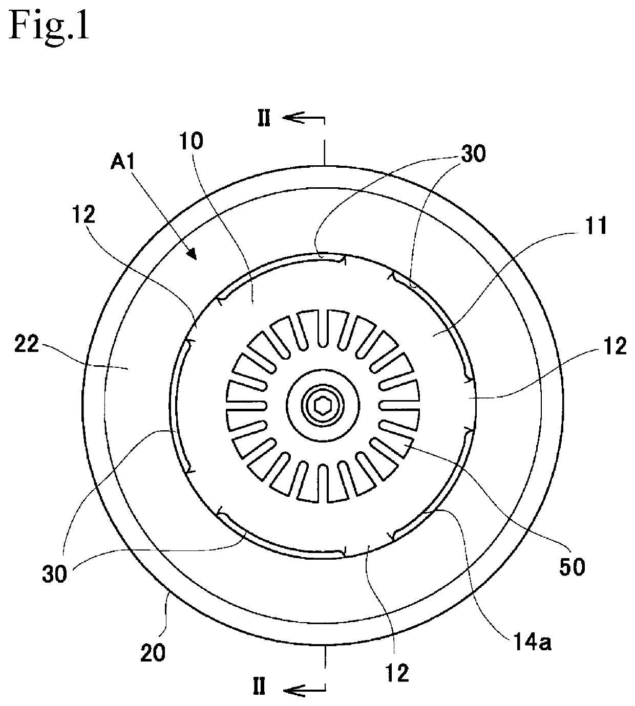
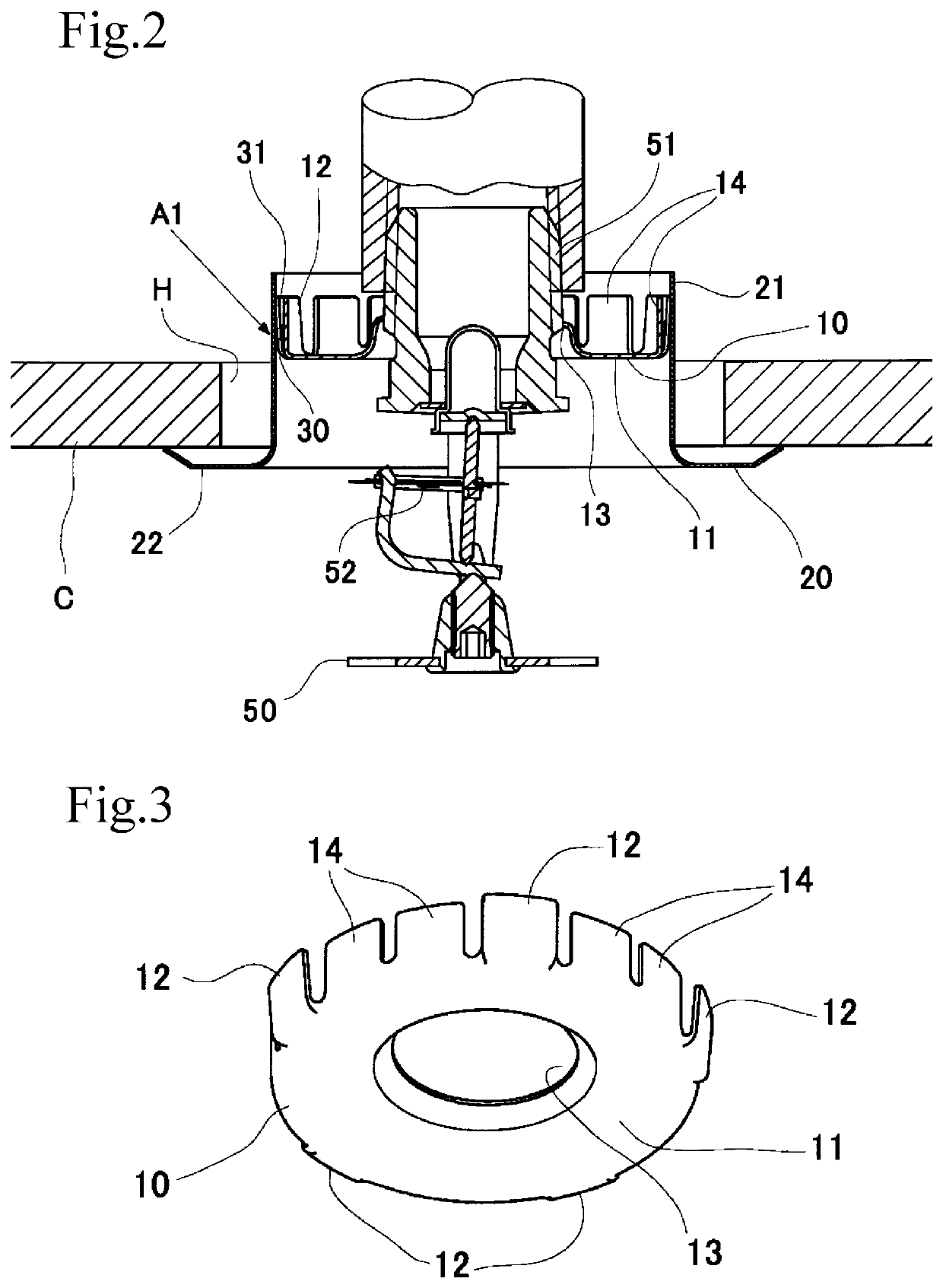
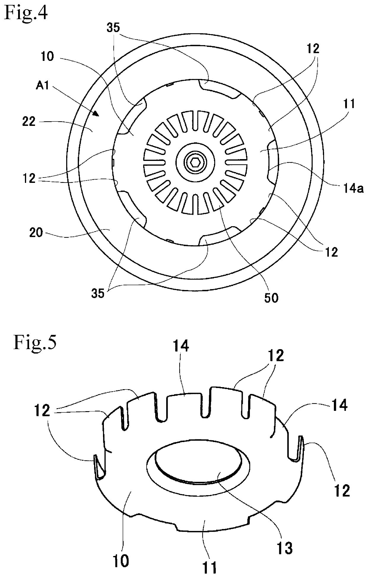
[0025]As FIGS. 1 and 2 illustrate, a sprinkler head accessory μl according to a first embodiment of the present invention is provided between a ceiling board C and a sprinkler head 50 disposed in a through hole H passing through the ceiling board C. The sprinkler head accessory μl has an inner ring 10 and an outer ring 20. The sprinkler head accessory μl is disposed so that the tube axial direction of each of the inner ring 10 and the outer ring 20 is parallel to the vertical direction in which the through hole H is formed. Each of the inner ring 10 and the outer ring 20 is made of metal and constituted by, for example, a steel plate. Alternatively, each of the inner ring 10 and the outer ring 20 may be constituted by, for example, a stainless-steel plate or a brass plate. In addition, each of the inner ring 10 and the outer ring 20 may be made of a material other than metal and may be made of, for example, plastic.

[0026]The inner ring 10 is disposed betwee...


PUM


Abstract

A sprinkler head accessory includes an inner ring attached to a sprinkler head and an outer ring hiding the edge of a ceiling hole through which the sprinkler head passes. The inner ring has a partition portion facing the outer ring with a gap therebetween. A ventilation portion constituted by the gap through which the indoor side of a ceiling board and the back side of the ceiling board communicate with one another is provided between the outer ring and the partition portion.

Description

BACKGROUND OF THE INVENTION1. Field of the Invention[0001]The present invention relates to an accessory of a sprinkler head installed in a building.2. Description of the Related Art[0002]Sprinkler systems are installed in buildings. Upon detecting heat of a fire, such a sprinkler system operates automatically and sprinkles water to extinguish the fire. A nozzle provided in a sprinkler head is connected to a pipe connected to a water supply source. In normal times, the nozzle is in a closed state by a valve, which is supported by a heat-activated unit, being closed. If a fire breaks out, in response to the heat, the heat-activated unit operates to release the valve in the closed state, and the water filled in the pipe is discharged through the nozzle. The sprinkler head has, on an extension of an outlet of the nozzle, a deflector that scatters water in all directions. The water that has collided with the deflector is sprinkled over a predetermined range, thereby suppressing and extin...

Claims


Application Information

Patent Timeline
Patent Type & Authority Applications(United States)
IPC IPC(8): A62C35/68F24F7/00B05B15/65
CPCA62C35/68B05B15/65F24F7/00A62C31/28A62C37/11
Inventor KOIWA, YASUAKI
Owner SENJU SPRINKLER
Why Eureka
Try Eureka