

Primary controller applied to a primary side of a power converter and operational method thereof
a technology of power converter and controller, applied in the direction of power conversion system, dc-dc conversion, instruments, etc., can solve the problems of reducing affecting the operation of the primary controller, and the ripple of the output voltage vout being too large to meet the specification, so as to achieve the effect of suppressing rippl
- Summary
- Abstract
- Description
- Claims
- Application Information
AI Technical Summary
Benefits of technology
Problems solved by technology
Method used
Image

Examples
first embodiment
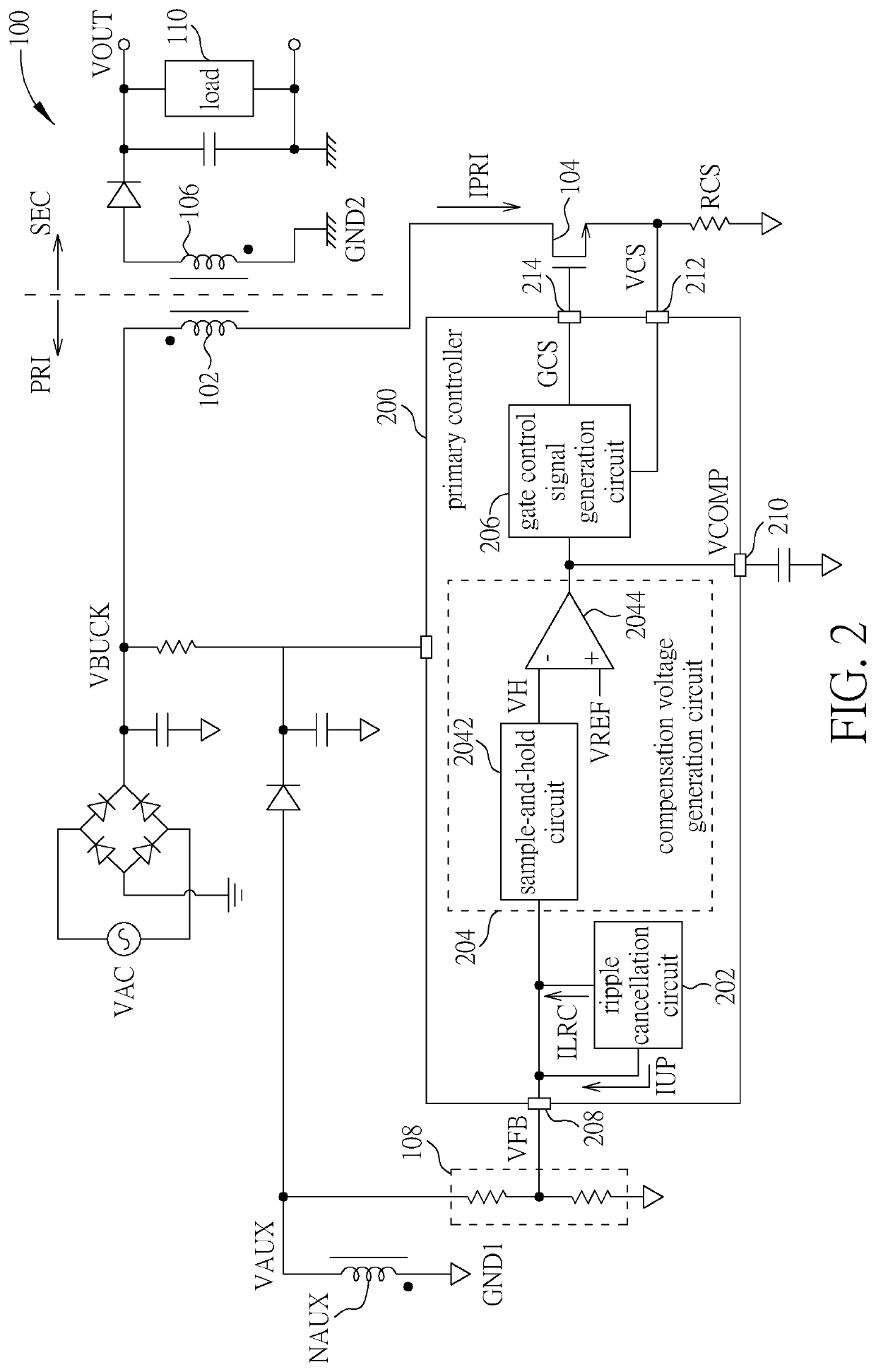
[0017]Please refer to FIG. 2. FIG. 2 is a diagram illustrating a primary controller 200 applied to a primary side PRI of a power converter 100 according to the present invention, wherein the primary controller 200 includes a ripple cancellation function. The primary controller 200 includes a ripple cancellation circuit 202, a compensation voltage generation circuit 204, and a gate control signal generation circuit 206, potential of ground GND1 of the primary side PRI of the power converter 100 are not necessarily equal to potential of ground GND2 of a secondary side SEC of the power converter 100, and the converter 100 is a flyback power converter. In addition, the power converter 100 can operate in a quasi-resonant mode (QRM), or a continuous-conduction mode (CCM), or a discontinuous-conduction mode (DCM). As shown in FIG. 2, the ripple cancellation circuit 202 is coupled to a feedback pin 208 of the primary controller 200, and the compensation voltage generation circuit 204 is cou...
second embodiment
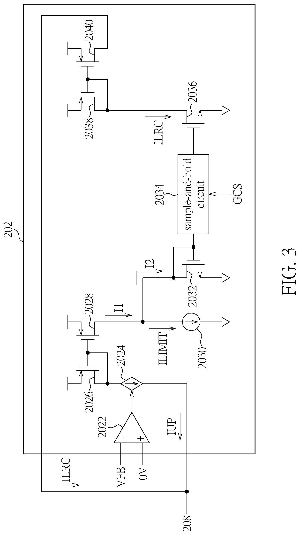
[0024]In addition, please refer to FIGS. 2, 3, 5-9. FIG. 9 is a flowchart illustrating an operational method applied to a primary controller of a primary side of a power converter according to the present invention. The operational method of FIG. 9 is illustrated using the power converter 100 and the primary controller 200 in FIG. 2, the ripple cancellation circuit 202 in FIG. 3, the DC voltage VBUCK, the regulation current ILRC, and the regulation voltage VLRC in FIG. 5, the output voltage VOUT in FIG. 6, the primary controller 600 in FIG. 7, and the ripple cancellation circuit 602 in FIG. 8. Detailed steps are as follows:
[0025]Step 900: Start.
[0026]Step 902: The ripple cancellation circuit 202 generates the adjustment during the turning-on of the power switch 104 according to the current IUP flowing through the feedback pin 208 of the primary controller 200.
[0027]Step 904: The compensation voltage generation circuit 204 generates the compensation voltage VCOMP of the compensation ...
PUM
 Abstract
Description
Claims
Application Information