Radio frequency power amplifier module

A technology for power amplifiers and radio frequency power, applied in power amplifiers, amplifiers, amplifiers with semiconductor devices/discharge tubes, etc., can solve the problems of increasing charge pumps, increasing the area of ​​radio frequency switches 20, increasing interference, etc., to achieve increased The effect of large drive capacity

Active Publication Date: 2019-05-28
RDA MICROELECTRONICS SHANGHAICO LTD
View PDF11 Cites 7 Cited by
  • Summary
  • Abstract
  • Description
  • Claims
  • Application Information

AI Technical Summary

Problems solved by technology

The disadvantage of this solution is: if the clock signal frequency of the charge pump 22 is reduced, in order to make the negative voltage output by the charge pump 22 reach the same driving capability, it is necessary to increase the capacitance used by the charge pump 22, which will increase the frequency of the RF switch. 20 area
The disadvantage of this solution is: if the distance between the charge pump 22 and the radio frequency core 21 is increased, the area of ​​the radio frequency switch 20 will also be increased
The disadvantage of this solution is: if the clock signal frequency of the charge pump 22 is increased, the interference of the clock signal of the charge pump 22 on the radio frequency switch 20 will increase
The disadvantage of this solution is: if the capacitance used by the charge pump 22 is increased, the area of ​​the RF switch 20 will be increased

Method used


Image

  • Radio frequency power amplifier module
  • Radio frequency power amplifier module
  • Radio frequency power amplifier module

Examples


Embodiment Construction

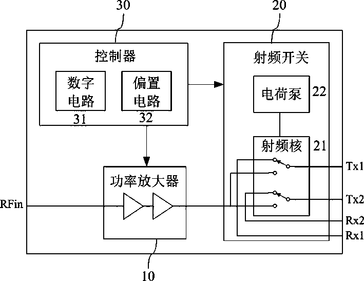
[0028] see figure 2 , which is Embodiment 1 of the radio frequency power amplifier module provided by this application. The radio frequency power amplifier module includes a power amplifier 10 , a radio frequency switch 20 and a controller 30 .

[0029]The power amplifier 10 includes one or more amplifying channels, which are respectively used to amplify the power of radio frequency signals in one or more frequency bands. The power amplifier 10 usually adopts a process with superior radio frequency performance, such as gallium arsenide, gallium nitride, and radio frequency CMOS process.

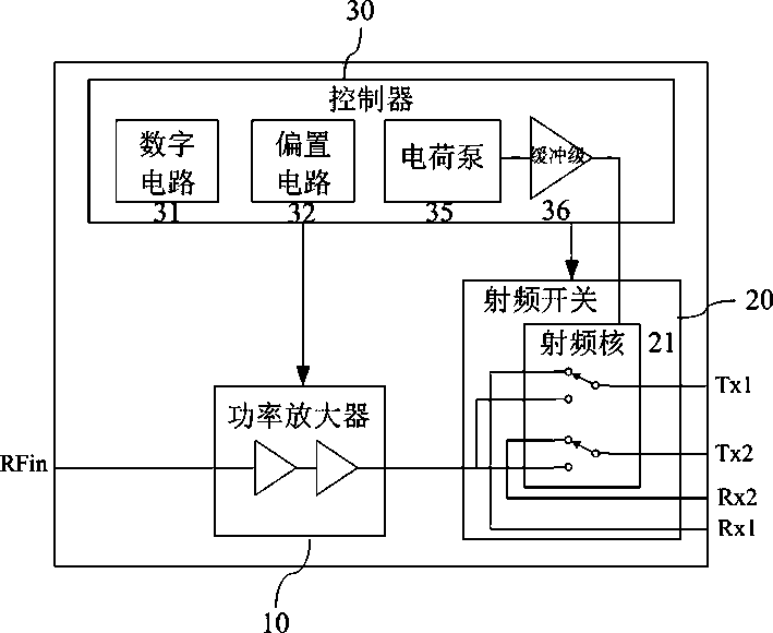
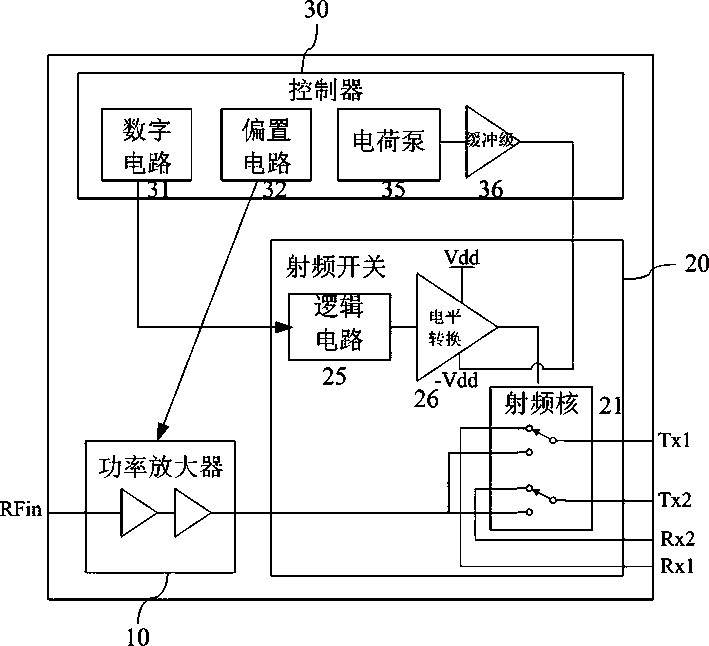
[0030] The radio frequency switch 20 further includes a radio frequency core 21 . The radio frequency core 21 is used to switch between amplifying channels of different frequency bands, and is also used to switch between transmitting channels and receiving channels. The radio frequency core 21 also uses the negative voltage output by the buffer stage 36 to negatively bias the disconnected...


PUM


Abstract

The invention discloses a radio frequency power amplifier module which comprises a power amplifier, a radio frequency switch and a controller. Wherein the radio frequency switch further comprises a radio frequency core. The radio frequency core is used for switching between amplification channels of different frequency bands and switching between a transmitting channel and a receiving channel. Theradio frequency core also uses the second negative voltage to perform negative voltage bias on the disconnected channel. The controller further comprises a charge pump and a buffer stage circuit. Thecharge pump is used for generating a first negative voltage. The buffer stage circuit is used for raising the first negative voltage to a second negative voltage. According to the invention, the charge pump is changed to be integrated into the controller. The radio frequency switch and the controller are usually manufactured on different substrate materials by adopting different processes, so that adverse effects of clock signals of the charge pump on the performance of the radio frequency switch are avoided. In addition, a buffer stage circuit is additionally arranged behind the charge pump,and a certain power supply rejection ratio is provided for restraining ripples on negative voltage output by the charge pump.

Description

technical field [0001] This application relates to a radio frequency power amplifier module including a power amplifier, a radio frequency switch and a controller. Background technique [0002] In a mobile terminal, a radio frequency power amplifier (RF power amplifier, RF PA for short) is used to amplify the power of a radio frequency signal to be transmitted, and then feed it to an antenna for external transmission. With the development of mobile communication technology, a mobile terminal needs to be compatible with more and more communication systems and frequency bands. In order to reduce the cost and size of the mobile terminal, the RF power amplifier is designed to cover as many frequency bands as possible, which introduces an RF switch (RF Switch) and a controller (controller). [0003] see figure 1 , which is an existing radio frequency power amplifier module (PA Module). The radio frequency power amplifier module includes a power amplifier 10 , a radio frequency...

Claims


Application Information

Patent Timeline
Patent Type & Authority Applications(China)
IPC IPC(8): H03F3/195H03F3/217H03F3/213H03F3/21G05F1/46
CPCY02D30/70
Inventor 王月林郑胜侯竟骁贾斌
Owner RDA MICROELECTRONICS SHANGHAICO LTD
Why Eureka
Try Eureka