
Providing a programmable inductor to enable wide tuning range

a programmable inductor and tuning range technology, applied in the direction of tunable filters, filtering, discontnuous tuning with seperate pretuned circuits, etc., can solve the problems of design trade-offs and corresponding limits on size, performance, power consumption and cost, and achieve the effect of reducing the impedance variation of the tuning network

Active Publication Date: 2021-10-21
SILICON LAB INC
View PDF0 Cites 0 Cited by
  • Summary
  • Abstract
  • Description
  • Claims
  • Application Information

AI Technical Summary

Problems solved by technology

However, there are several design constraints that come into play when designing a network for use over a wide frequency range, particularly when seeking to balance countervailing considerations including circuit size, power consumption, component quality and so forth.
Available solutions suffer from drawbacks in these different criteria, which lead to design tradeoffs and corresponding limits on size, performance, power consumption and cost.

Method used


Image

  • Providing a programmable inductor to enable wide tuning range
  • Providing a programmable inductor to enable wide tuning range
  • Providing a programmable inductor to enable wide tuning range

Examples


Embodiment Construction

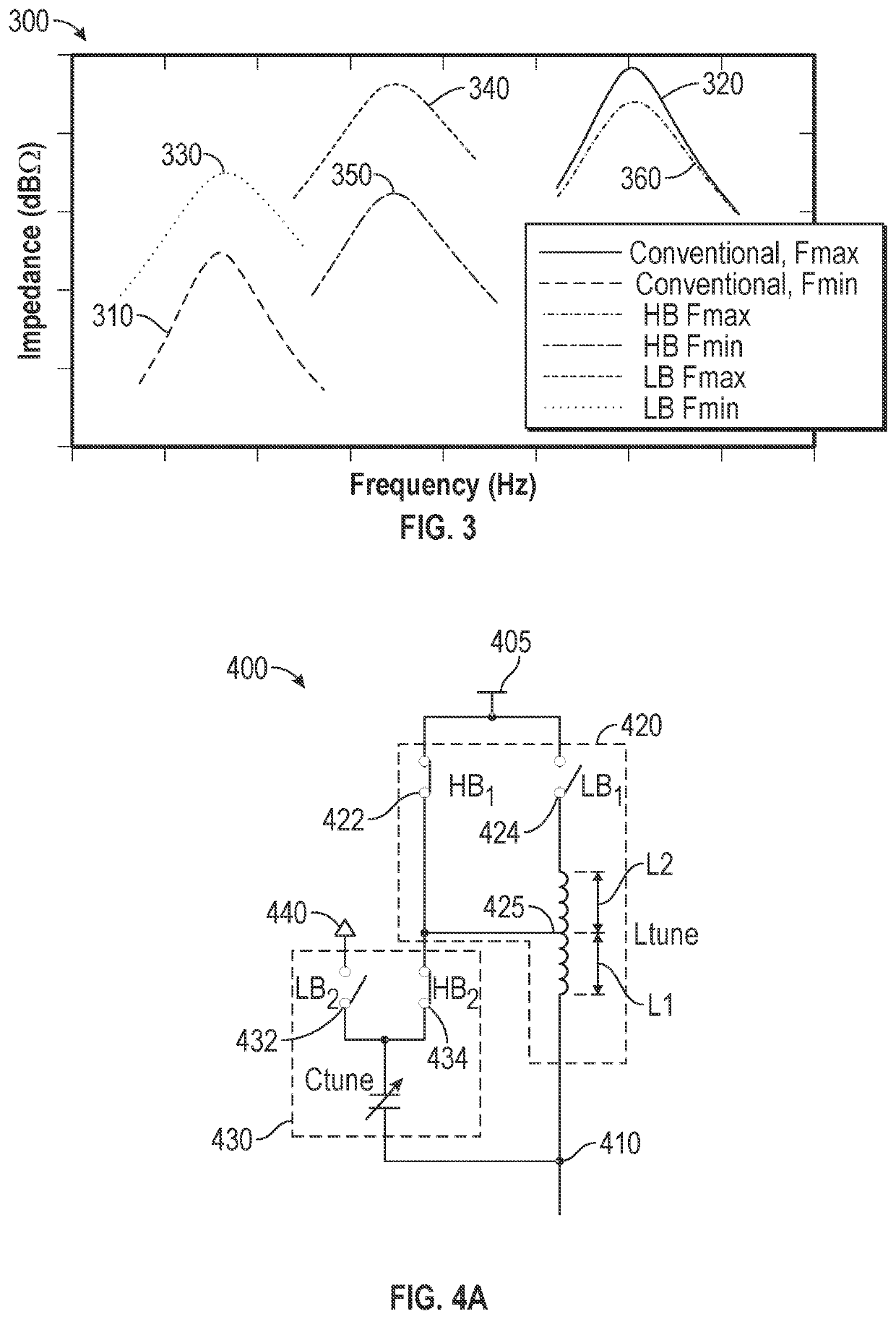
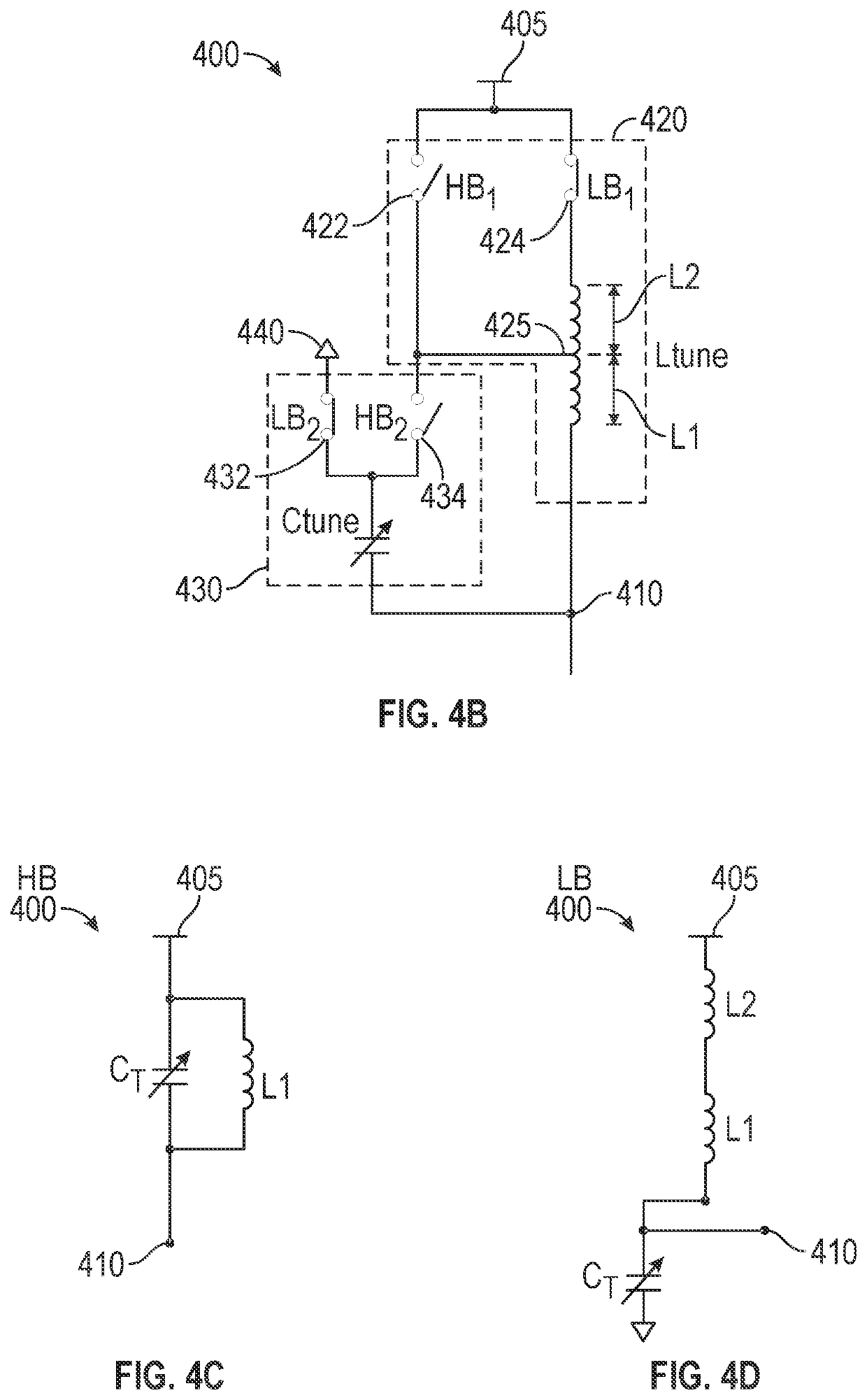
[0027]In various embodiments, a resonant tank circuit is provided that includes both a programmable capacitor and a programmable inductor. By using a programmable inductor, a wide frequency range of operation may be covered, while at the same time not consuming too much chip area and system current / power. Still further as described herein, in different implementations the amount of tuning capacitance can be reduced, and an effective impedance of the resonant tank circuit may have less variation over the frequency range.

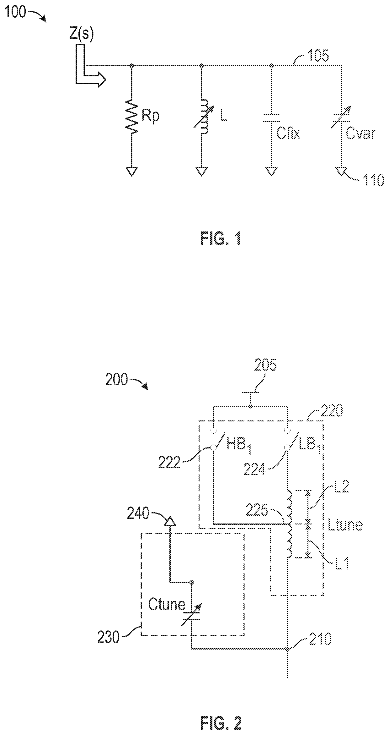
[0028]Referring now to FIG. 1, shown is a high level schematic diagram of a resonant tank circuit (also referred to as a tuning network) in accordance with an embodiment. As shown in FIG. 1, resonant tank circuit 100 includes a plurality of components in the embodiment shown, these components couple between a signal line 105 and a reference voltage node 110. In different embodiments, note that signal line 105 may couple to an output (or an input) of a given circuit su...


PUM


Abstract

In one embodiment, a tuning network includes: a controllable capacitance; a first switch coupled between the controllable capacitance and a reference voltage node; a second switch coupled between the controllable capacitance and a third switch; the third switch coupled between the second switch and a second voltage node; a fourth switch coupled between the second voltage node and a first inductor; the first inductor having a first terminal coupled to the fourth switch and a second terminal coupled to at least the second switch; and a second inductor having a first terminal coupled to the second terminal of the first inductor and a second terminal coupled to the controllable capacitance.

Description

[0001]This application is a continuation of U.S. patent application Ser. No. 16 / 850,215, filed Apr. 16, 2020, the content of which is hereby incorporated by reference.BACKGROUND[0002]An inductor-capacitor (LC) tank or network is commonly employed as a loading component in radio frequency (RF) circuits such as amplifiers, filters, mixers and so forth to provide sufficient gain and filtering at high frequency. Conventionally, a fixed-value inductor is used along with a variable capacitor (or a programmable capacitor array), so that the operating frequency can be tuned.[0003]However, there are several design constraints that come into play when designing a network for use over a wide frequency range, particularly when seeking to balance countervailing considerations including circuit size, power consumption, component quality and so forth. Available solutions suffer from drawbacks in these different criteria, which lead to design tradeoffs and corresponding limits on size, performance,...

Claims


Application Information

Patent Timeline
Patent Type & Authority Applications(United States)
IPC IPC(8): H03J5/24H03H11/04
CPCH03J5/244H03H11/04H03F1/42H03H7/0115H03H7/1775H03H2210/025H03H2210/026H03H2001/0078H03J3/22
Inventor SUN, RUIFENGCOBAN, ABDULKERIM
Owner SILICON LAB INC
Learn More