Elbow joint prostheses

a technology for elbow joints and prostheses, applied in the field of elbow joint prostheses, can solve problems such as the deterioration of the function of the elbow joints

Active Publication Date: 2021-10-28
HOWMEDICA OSTEONICS CORP
View PDF0 Cites 0 Cited by
  • Summary
  • Abstract
  • Description
  • Claims
  • Application Information

AI Technical Summary

Problems solved by technology

The elbow joint function can deteriorate for a number of reasons, including osteoporosis, cartilage wear, trauma, and other reasons.

Method used


Image

  • Elbow joint prostheses
  • Elbow joint prostheses
  • Elbow joint prostheses

Examples


Embodiment Construction

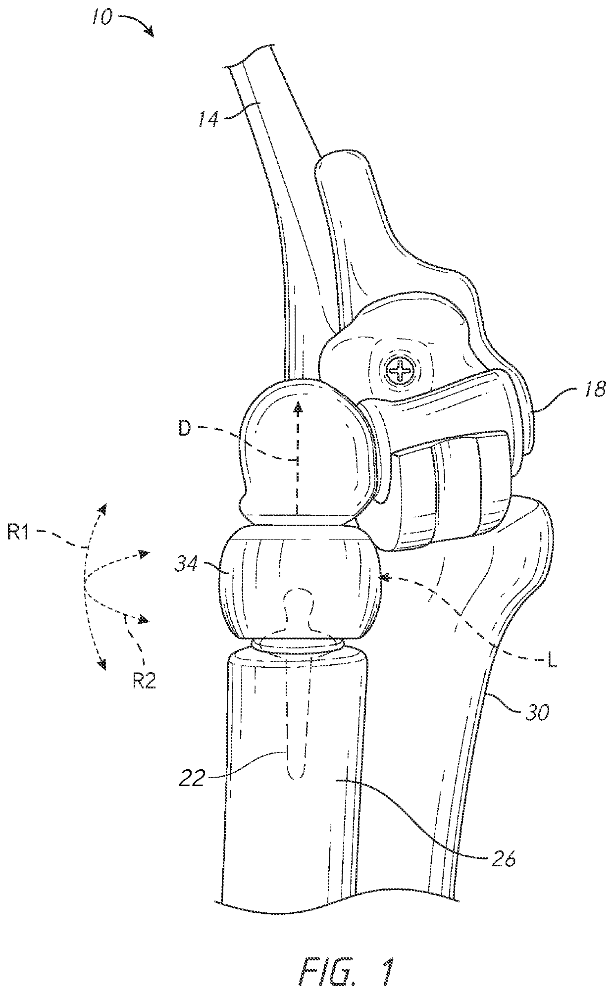
[0064]This application is directed to an elbow joint prostheses and methods that can be used in elbow joint replacement procedures, which can be used to correct elbow joint conditions including deformity, wear, osteoarthritis, and trauma. As discussed in greater detail below the apparatuses and methods herein reduce risk of dislocation and decoupling, and also facilitate implantation and removal of the apparatuses during surgical procedures, and provide ranges of sizes to better fit a full range of patients.

[0065]I. Elbow Joint Components and Force Dynamics

[0066]FIG. 1 shows an elbow joint prosthesis 10. The prosthesis 10 has a humeral stem 14, a humeral spool 18, and a radial stem 22. The radial stem 22 is shown embedded in a radius 26. The prosthesis 10 also can have an ulnar stem (not shown) embedded in the ulna 30. A radial head 34 is disposed on the radial stem 22 and is coupled with one end of the humeral spool 18. The radial head 34 can be capable of bipolar articulation. For...


PUM


Abstract

A radial head assembly is provided that includes a stem, a collar, a locking ring, and an articular member. The stem has a convex articular head on one end thereof. The locking ring has a ring wall, which has a ring opening. The ring wall has an angular outer surface and a slot configured to permit the ring wall to radially expand. The angular outer surface engages an angular portion of an interior surface of the collar. The articular member and the locking ring define an articular space within the collar. The articular space is configured to receive the convex articular head.

Description

INCORPORATION BY REFERENCE[0001]The entire contents of U.S. Provisional Patent Application No. 62 / 740,790, filed on Oct. 3, 2018, are hereby incorporated by reference herein in their entireties, forming part of the present disclosure. Any feature, structure, material, method, or step that is described and / or illustrated in any embodiment in the foregoing provisional patent application can be used with or instead of any feature, structure, material, method, or step that is described in the following paragraphs of this specification and / or illustrated in the accompanying drawings.BACKGROUND OF THE INVENTIONField of the Invention[0002]This application relates to an elbow joint prostheses and methods for assembling, fitting and implanting the same.Description of the Related Art[0003]Elbow prostheses are sometimes implanted in patients with deteriorating elbow joint function. The elbow joint function can deteriorate for a number of reasons, including osteoporosis, cartilage wear, trauma,...

Claims


Application Information

Patent Timeline
Patent Type & Authority Applications(United States)
IPC IPC(8): A61F2/38
CPCA61F2/3804A61F2002/30495A61F2/4637A61F2002/3827A61F2002/3809A61F2/4605A61F2002/30331A61F2002/30476A61F2002/30579A61F2002/30494A61F2002/30528A61F2/38A61F2002/30383A61F2002/30602A61F2002/3813
Inventor KARTHOLL, MATTHEW VICTORPARKER, BRAD ALANFARLEY, KEVIN ALIKAKOEPKE, RYAN D.
Owner HOWMEDICA OSTEONICS CORP
Why Eureka
Try Eureka