
Vehicular around view monitoring system through adjustment of viewing angle of camera, and method thereof

Inactive Publication Date: 2021-10-28
MEEKYUNGTEC CO LTD
View PDF0 Cites 0 Cited by
  • Summary
  • Abstract
  • Description
  • Claims
  • Application Information

AI Technical Summary

Benefits of technology

The invention is about a system and method for displaying the image from a camera in a vehicle's rearview mirror. The system can adjust the angle of view of the camera based on the vehicle's speed and the driver's state, which makes the image look better and more real. This helps to improve the driver's overall sense of touch and removes any feeling of difference between the image on the screen and the real world.

Problems solved by technology

In general, when operating a vehicle, a driver may easily recognize and determine a situation ahead in a heading direction, but have difficulties in easily recognizing the left and right sides and the rear side of the vehicle, which correspond to dead zones for a driver's view.
Therefore, such conventional view securing units have a mirror structure that enables a driver to recognize an object through a simple light reflection action, and thus form a narrow viewing angle such that a driver's view is blocked by a person, baggage or trailer in a rear seat, and the visibility and reflection range of a subject are inevitably extremely limited.

Method used


Image

  • Vehicular around view monitoring system through adjustment of viewing angle of camera, and method thereof
  • Vehicular around view monitoring system through adjustment of viewing angle of camera, and method thereof
  • Vehicular around view monitoring system through adjustment of viewing angle of camera, and method thereof

Examples


Embodiment Construction

[0039]The above-described objectives, features and advantages will be more clarified through the following embodiments related to the accompanying drawings.

[0040]The descriptions of specific structures or functions are only exemplified to describe embodiments according to the concept of the present disclosure, and the embodiments according to the concept of the present disclosure may be carried out in various manners, and should not be construed as being limited to the embodiments described in the specification of the present application.

[0041]Since the embodiments according to the concept of the present disclosure can be modified in various manners and have various forms, specific embodiments will be illustrated in the drawings and described in detail in the specification of the present application. However, the embodiments according to the concept of the present disclosure are not limited to the specific embodiments, but should be understood to include all modifications, equivalen...


PUM


Abstract

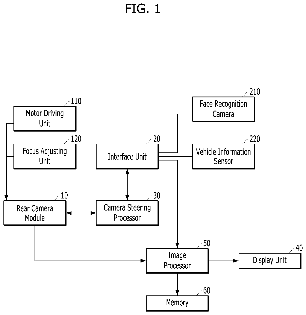
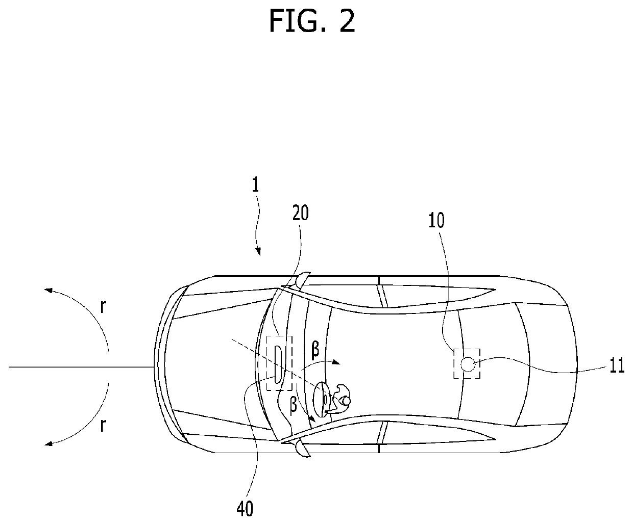
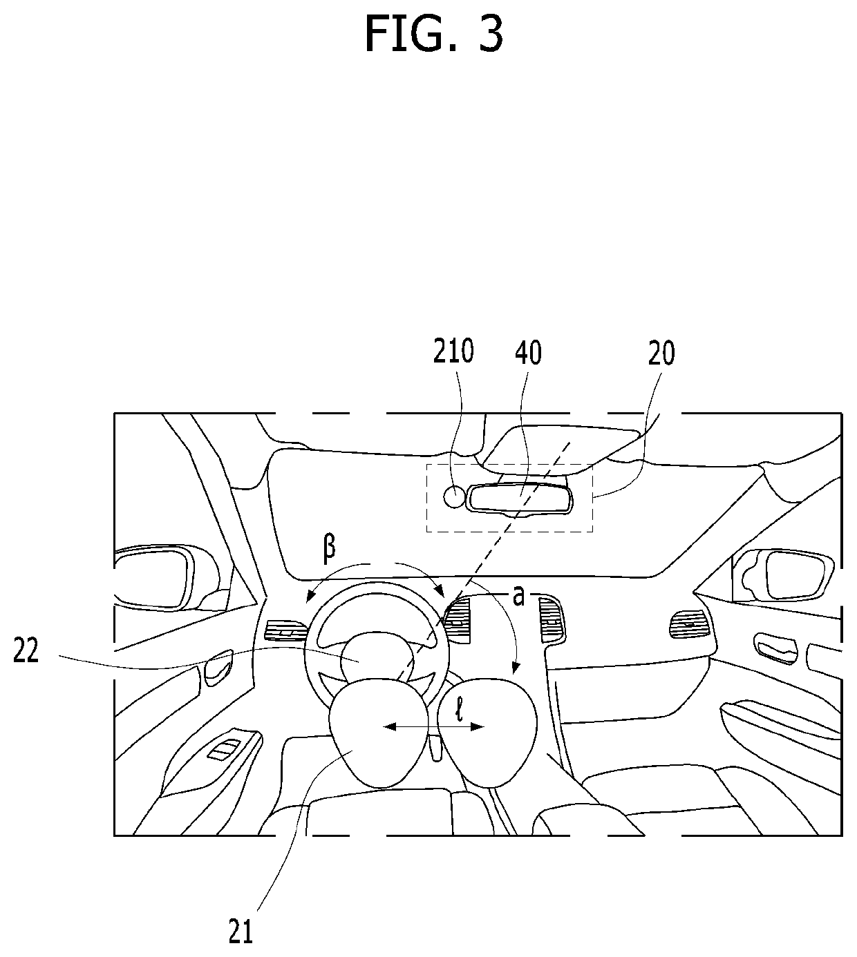
A vehicular AVM (Around View Monitoring) system may include: a rear camera module 10 mounted on an area of a vehicle and configured to acquire an image around the vehicle; an interface unit 20 configured to receive information on a turning angle α at which a driver's face 21 is turned to the left or right and / or a side-to-side displacement l by which the face 21 is moved to the left or right from the central axis of the driver's body; a camera steering processor 30 configured to adjust the angle θ of a camera 11 of the rear camera module 10 according to the information received by the interface unit 20; and an image processor 50 configured to control a display unit 40 to display an image of an area 41 matched with the information received by the interface unit 20, among the surrounding images of the vehicle.

Description

TECHNICAL FIELD[0001]The present disclosure relates to an AVM (Around View Monitoring) system that provides operational convenience by showing an image, obtained by capturing the surroundings of a vehicle, to a driver in a vehicle, and more particularly, to a vehicular AVM system capable of adjusting the viewing angle of a camera according to the driving state of a vehicle and the state of a driver, and a method thereof.[0002]Furthermore, the present disclosure relates to a vehicular AVM system capable of improving the intuition of an image provided by a display unit thereof, and a method thereof.BACKGROUND ART[0003]AVM refers to a system that displays an image around a vehicle, taken by a camera attached to the vehicle, on a monitor within the vehicle, and enables a driver to driven the vehicle while recognizing the situation around the vehicle through the image of the monitor.[0004]In general, when operating a vehicle, a driver may easily recognize and determine a situation ahead ...

Claims


Application Information

Patent Timeline
IPC IPC(8): B60R1/00B60R11/04H04N5/232H04N5/262G06F3/01G06K9/00
CPCB60R1/00B60R11/04H04N5/23299H04N5/2628G06F3/012B60R2011/0085G06K9/00845G06K9/00268H04N5/23219B60R2300/605B60R2300/20G06K9/00228B60R2300/8066B60R2300/101B60R2001/1215G06V20/59G06V40/161H04N23/611H04N23/695H04N23/90B60R1/26B60R1/28B60W50/14B60W40/02B60W30/18036B60K35/00H04N7/181B60W2050/146B60W2540/18B60Y2300/18033H04N23/57B60W2420/403G06V20/597G06V40/168
Inventor OH, SE BEENKIM, JUNG SU
Owner MEEKYUNGTEC CO LTD
Learn More