Method for accurate object tracking with color camera in multi planar scanners

Active Publication Date: 2021-10-28
ZEBRA TECH CORP
View PDF0 Cites 0 Cited by
  • Summary
  • Abstract
  • Description
  • Claims
  • Application Information

AI Technical Summary

Benefits of technology

The present invention is a method that enables accurate tracking of objects using two optical imaging assemblies with different fields of view. The first assembly captures an image and identifies an object of interest based on an associated indicia. The location of the object in the first image is mapped to a predicted location in a second image captured by the second assembly. This method allows for consistent and accurate tracking of objects as they move within the imaging environments of the two assemblies.

Problems solved by technology

At checkout systems, a barcode reader may not always identify items correctly.

Method used


Image

  • Method for accurate object tracking with color camera in multi planar scanners
  • Method for accurate object tracking with color camera in multi planar scanners
  • Method for accurate object tracking with color camera in multi planar scanners

Examples


Embodiment Construction

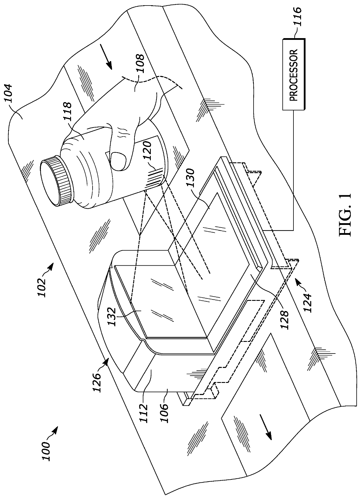
[0024]FIG. 1 illustrates a perspective view of an example point-of-sale (POS) system 100 in accordance with the teachings of this disclosure. In the example shown, the system 100 includes a workstation 102 with a counter 104 and a bi-optical (also referred to as “bi-optic”) barcode reader 106. The barcode reader 106 may also be referred to as a bi-optic scanner or an indicia reader. The POS system 100 may be managed by a store employee such as a clerk 108. In other cases, the POS system 100 may be part of a self-checkout lane wherein customers are responsible for checking out their own products.

[0025]The barcode reader 106 includes a housing 112 comprised of a lower housing 124 and a raised housing 126. The lower housing 124 may be referred to as a first housing portion and the raised housing 126 may be referred to as a tower or a second housing portion. The lower housing 124 includes a top portion 128 and houses an optical imaging assembly 130. In some embodiments, the top portion ...


PUM


Abstract

Methods for accurate object tracking are disclosed herein. An example the method includes receiving, from a first optical imaging assembly having a first field of view (FOV), a first image captured over the first FOV and based on a decode of an indicia associated with an object of interest, identifying the object of interest within the first image. The method further includes determining a location of the object of interest within the first image and mapping the location of the object of interest within the first image to a predicted location of the object of interest within a second image, the second image being received from a second optical imaging assembly having a second FOV and the second image being captured over the second FOV.

Description

BACKGROUND[0001]At checkout systems, a barcode reader may not always identify items correctly. For example, an item may be passed across a barcode reader but the item barcode may not be read. Additionally, an item may be tagged with an incorrect barcode. Accordingly, there is a need for systems to increase item identification accuracy.SUMMARY[0002]In an embodiment, the present invention is a method for accurate object tracking. The method begins by receiving, from a first optical imaging assembly having a first field of view (FOV), a first image captured over the first FOV and, based on a decode of an indicia associated with an object of interest, identifying the object of interest within the first image. The method continues by determining a location of the object of interest within the first image and mapping the location of the object of interest within the first image to a predicted location of the object of interest within a second image, the second image being received from a ...

Claims


Application Information

Patent Timeline
IPC IPC(8): G06K7/10G06K9/20G06K9/18G06K7/14G06V30/224
CPCG06K7/10574G06K7/1413G06K9/18G06K9/2054G07G1/0045G07G1/0054G07G3/006G06Q20/208G06Q20/4015G06Q20/4016G06V30/224G06V20/52G06V10/12
Inventor WILFRED, SAJANFJELLSTAD, CHRISTOPHER J.DAEMPFLE, VINCENT J.
Owner ZEBRA TECH CORP
Why Eureka
Try Eureka