LED bracket, LED device, and edge-lit backlight module

Inactive Publication Date: 2021-10-28
SHENZHEN CHINA STAR OPTOELECTRONICS SEMICON DISPLAY TECH CO LTD
View PDF0 Cites 0 Cited by
  • Summary
  • Abstract
  • Description
  • Claims
  • Application Information

AI Technical Summary

Benefits of technology

[0026]Advantages of the present invention: The LED bracket of the present invention comprises an insulating stand, and a conductive anode lead and a conductive cathode lead which are embedded in the insulating stand. The conductive anode lead and the conductive cathode lead comprise an anode pad and a cathode pad exposed from an upper surface of the insulating stand, respectively. The anode pad and the cathode pad are symmetrically arranged on the insulating stand. The present invention utilizes the symmetrically arranged metal pads to effectively solve a color difference problem of the LED device, im

Problems solved by technology

The direct-lit backlight module is configured such that a light source such as a cold cathode fluorescent lamp (CCFL) or a light emitting diode (LED) is disposed behind the liquid crystal panel, so the design and w

Method used


Image

  • LED bracket, LED device, and edge-lit backlight module
  • LED bracket, LED device, and edge-lit backlight module
  • LED bracket, LED device, and edge-lit backlight module

Examples


Embodiment Construction

is provided with reference to the accompanying drawings. However, the accompanying drawings are illustrative only and not intended to limit the invention. In the drawings:

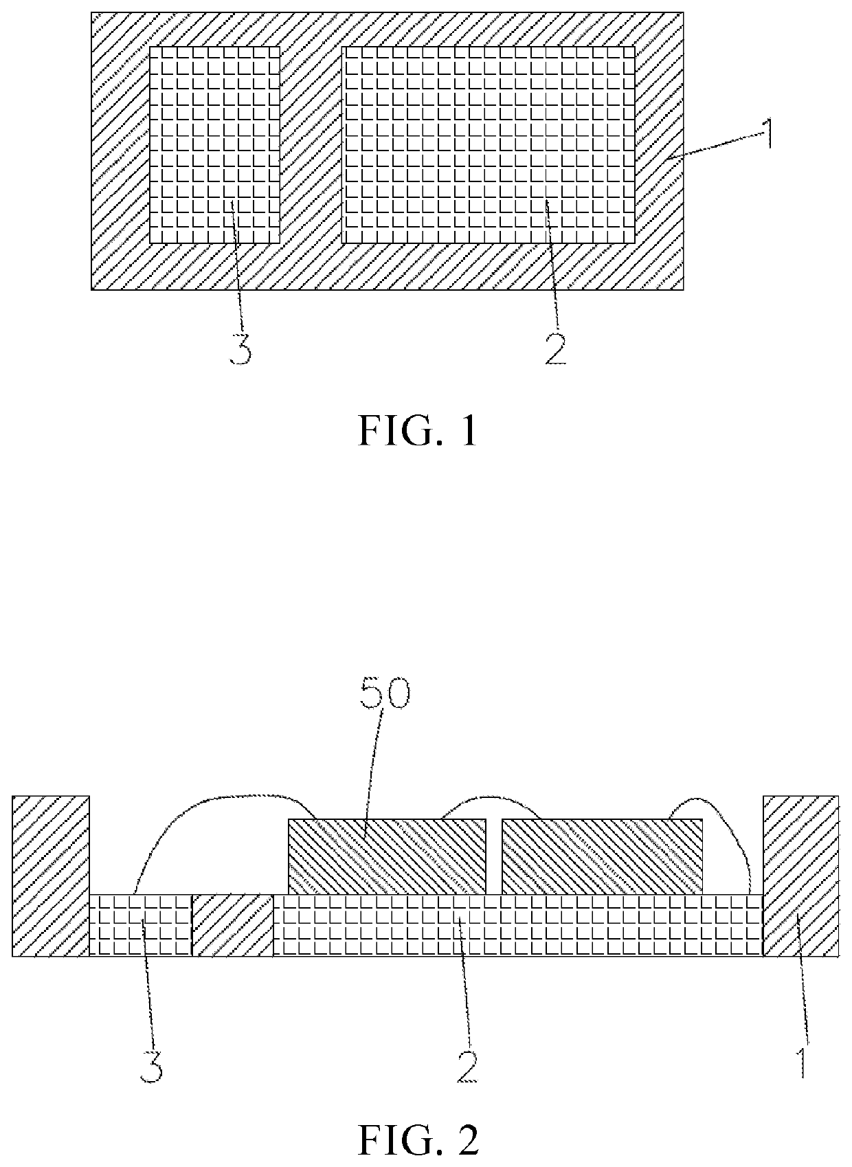
[0028]FIG. 1 is a schematic structural view illustrating a conventional light emitting diode (LED) bracket;

[0029]FIG. 2 is a schematic structural view illustrating a conventional LED device;

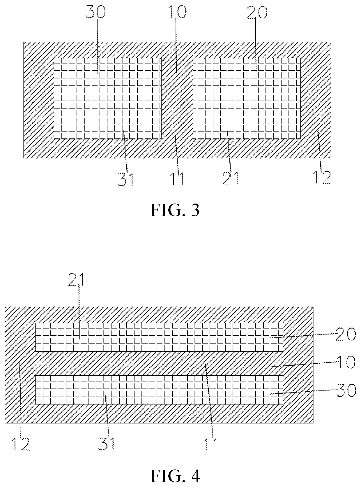
[0030]FIG. 3 is a schematic view illustrating an LED bracket of the present invention, wherein an anode pad and a cathode pad are arranged symmetrical to each other in a lengthwise direction of an insulating stand;

[0031]FIG. 4 is a schematic view illustrating the LED bracket of the present invention, wherein the anode pad and the cathode pad are arranged symmetrical to each other in the lengthwise direction of the insulating stand;

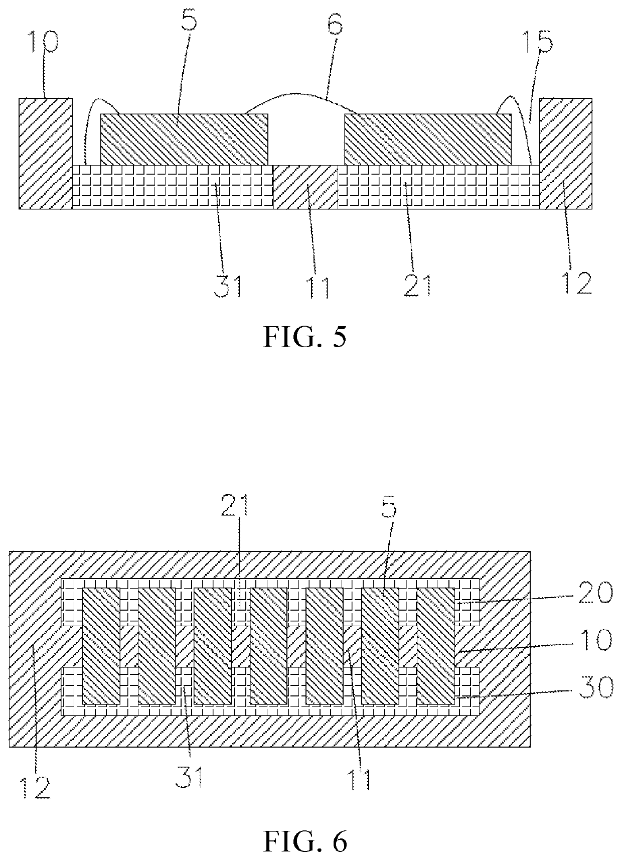
[0032]FIG. 5 is a schematic view illustrating that the LED bracket of the present invention is used to realize large-sized chip packaging;

[0033]FIG. 6 is a schematic view illustrating that the LED brac...


PUM


Abstract

The present invention provides a light emitting diode (LED) bracket, an LED device, and an edge-lit backlight module. The LED bracket includes an insulating stand, and a conductive anode lead and a conductive cathode lead which are embedded in the insulating stand. The conductive anode lead and the conductive cathode lead comprise an anode pad and a cathode pad exposed from an upper surface of the insulating stand. The anode pad and the cathode pad are arranged symmetrical to each other on the insulating stand. The present invention utilizes symmetrically arranged metal pads to effectively solve a color difference problem of the LED device, improve luminous efficiency and stability of the LED device, and realize large-sized chip packaging, high-efficiency flip-chip packaging, and high-voltage LED packaging.

Description

1. FIELD OF DISCLOSURE[0001]The present invention relates to a field of display devices and in particular, to a light emitting diode (LED) bracket, an LED device, and an edge-lit backlight module.2. DESCRIPTION OF RELATED ART[0002]In recent years, liquid crystal displays (LCDs) have become the mainstream of current displays because they can truly present real colors in nature. Most of the LCD devices on the market are backlight type LCD devices, including liquid crystal panels and backlight modules. Generally, a structure of a liquid crystal panel is constituted by a color filter (CF) substrate, a thin film transistor (TFT) array substrate, and a liquid crystal layer disposed between the two substrates. The operation principle of the liquid crystal panel is to control rotation of liquid crystal molecules of the liquid crystal layer by applying a driving voltage on the two glass substrates, and refract light from the backlight module to generate a picture.[0003]Since the liquid cryst...

Claims


Application Information

Patent Timeline
IPC IPC(8): H01L25/075H01L33/62F21V8/00
CPCH01L25/0753H01L33/62H01L24/45G02B6/0068G02B6/0073G02B6/0083H01L2224/48137H01L2224/48091H01L2224/48257H01L2224/48247H01L2924/00014H01L2924/12041H01L2224/48227H01L2224/48237H01L2224/49109H01L24/48H01L24/16H01L2224/16225H01L24/49H01L2224/45099H01L2224/45144
Inventor LIN, YUEXIAXIONG, CHONG
Owner SHENZHEN CHINA STAR OPTOELECTRONICS SEMICON DISPLAY TECH CO LTD
Why Eureka
Try Eureka