
Improvements in and relating to road safety rail systems and parts and fittings therefor

Active Publication Date: 2021-11-11
VALMONT HIGHWAY INT PTY LTD
View PDF0 Cites 0 Cited by
  • Summary
  • Abstract
  • Description
  • Claims
  • Application Information

AI Technical Summary

Benefits of technology

The patent is about an impact head that has a tapered axial orifice, which reduces the size of the orifice compared to the rail entry point. This design helps to improve the impact head's performance during use.

Problems solved by technology

However, known terminal ends suffer from performance limitations and short comings which can include:Complicated construction requiring modification (e.g. removing material) from a large number of rails over a long distance, which is labour intensive, time consuming and expensive;Potential instability of the constricting head;Difficulties transitioning the rail from an above ground height down to ground level;Requiring tensioned cables;Complicated head designs to deform the rail in one or more dimensions;Creating hazards for vehicles which detract from any energy absorbing capability of the terminal end including but not limited to creating a potential ramp for an impacting vehicle;The potential for the rail to buckle and fail to adequately and / or safely absorb energy.
This is critical when impacting into the end of the rail system as the rail can form a direct hazard.

Method used


Image

  • Improvements in and relating to road safety rail systems and parts and fittings therefor
  • Improvements in and relating to road safety rail systems and parts and fittings therefor
  • Improvements in and relating to road safety rail systems and parts and fittings therefor

Examples


Embodiment Construction

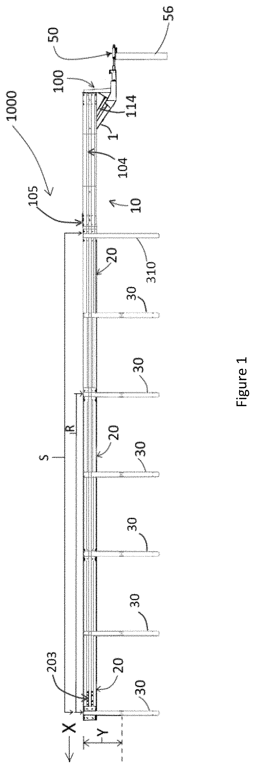
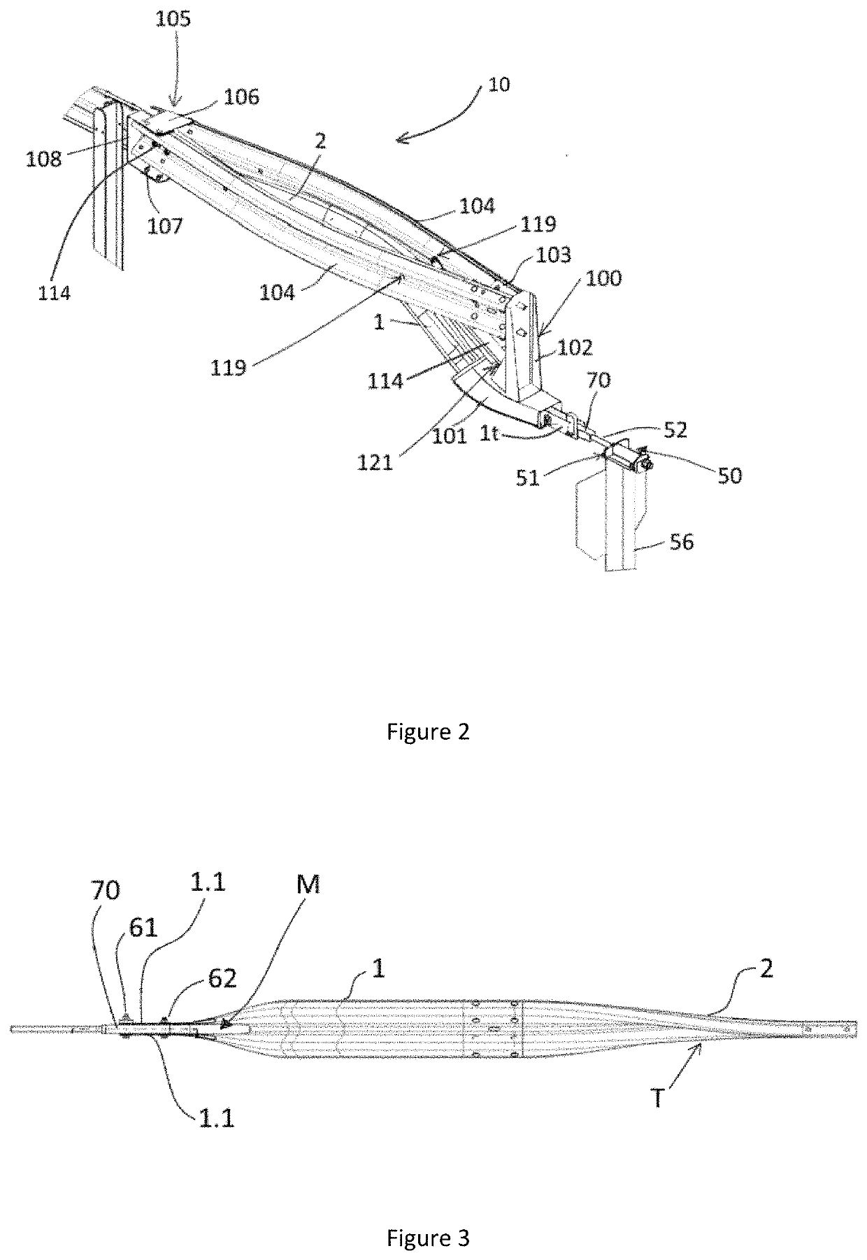
[0088]With respect to FIGS. 1-18 there is shown the terminal end section (TES) 1000 of a road safety rail system, the rest of the rail system extending in direction X, is not shown as it consists of standard posts and sequentially connected rails in the form of W-beams (system rails) as is well known in the art. Unless otherwise stated the posts and rails of the TES 1000 are connected by bolts as is standard industry practice.

[0089]Stationary Component—see in particular FIGS. 1-4, and 11

[0090]The TES 1000 has a stationary component indicated by double headed arrow S having:[0091]a plurality of sequentially connected standard terminal end (STE)-rails 20 in the form of W-beams; and[0092]sequentially connected formed terminal end (FTE)-rails 1,2 also in the form of W-beams.

[0093]The STE rails 20 are supported above the ground at a set height Y, by a plurality of terminal posts in the form of I-beam posts 90, which provide a rail height of substantially 780 mm.

[0094]In the embodiment sh...


PUM


Abstract

A road safety rail system comprising at least one continuous rail, or a plurality of sequentially connected system rails, forming a main body of a barrier, which are supported above ground by one or more ground engaging posts, wherein the system also comprises a terminal end section (TES) having an upstream end and a downstream end, the TES including:a stationary component comprising one or more standard terminal end (STE)-rails at the downstream end connected to at least one formed terminal end (FTE)-rail located at the upstream end of the TES,the STE rails being supported at a set horizontal axis height above ground level by a plurality of posts;wherein the at least one FTE-rail(s)-include(s) a twist from a primarily vertical orientation to a primarily horizontal orientation;Wherein the at least one FTE rail(s) bends down from a set horizontal axis height Y above ground level to a horizontal axis height being at, or near ground level;a moving energy absorbing component comprising an impact head including a base and upright projection, the base comprising an axial orifice extending from a downstream entry point to an upstream exit point, through which an upstream terminus of an FTE rail is passed before the FTE rail is directly or indirectly connected to a releasable connection point coupled to a ground anchor;wherein the impact head is connected via at least one beam to a post detacher element located downstream of said impact head a pre-determined distance therefrom.

Description

TECHNICAL FIELD[0001]The present invention relates to improvements in and relating to road safety rail systems and parts and fittings therefor. In particular, the present invention relates to an end terminal system for a road safety rail system.BACKGROUND ART[0002]The construction of terminal ends for safety rail systems such as for example guardrail systems or road barriers including W-beams and Thrie-beams are well known. However, known terminal ends suffer from performance limitations and short comings which can include:[0003]Complicated construction requiring modification (e.g. removing material) from a large number of rails over a long distance, which is labour intensive, time consuming and expensive;[0004]Potential instability of the constricting head;[0005]Difficulties transitioning the rail from an above ground height down to ground level;[0006]Requiring tensioned cables;[0007]Complicated head designs to deform the rail in one or more dimensions;[0008]Creating hazards for ve...

Claims


Application Information

Patent Timeline
IPC IPC(8): E01F15/14E01F15/04
CPCE01F15/146E01F15/0407E01F15/143E01F15/0461
Inventor DIEHL, ANDREW KARLSARRATT, ANDREW MICHAELREADMAN, KENNETH LLOYDNEWMAN, ALEXANDER PETER HANNIBALBEALE, ANDREW JOHNALLINGTON, CHRISTOPHER JAMESBROWN, LEIGH ROBERT
Owner VALMONT HIGHWAY INT PTY LTD
Features
  • Generate Ideas
  • Intellectual Property
  • Life Sciences
  • Materials
  • Tech Scout
  • Unparalleled Data Quality
  • Higher Quality Content
  • 60% Fewer Hallucinations
Learn More