Optical keyswitch
a key switch and optical technology, applied in the field of optical keyswitch, can solve the problems of poor pressing feeling, easy damage to the membrane circuit, inability to satisfy the user's expectation, etc., and achieve the effect of reducing the interference of external light, fast and accurate triggering, and enhancing triggering accuracy
- Summary
- Abstract
- Description
- Claims
- Application Information
AI Technical Summary
Benefits of technology
Problems solved by technology
Method used
Image
Examples
first embodiment
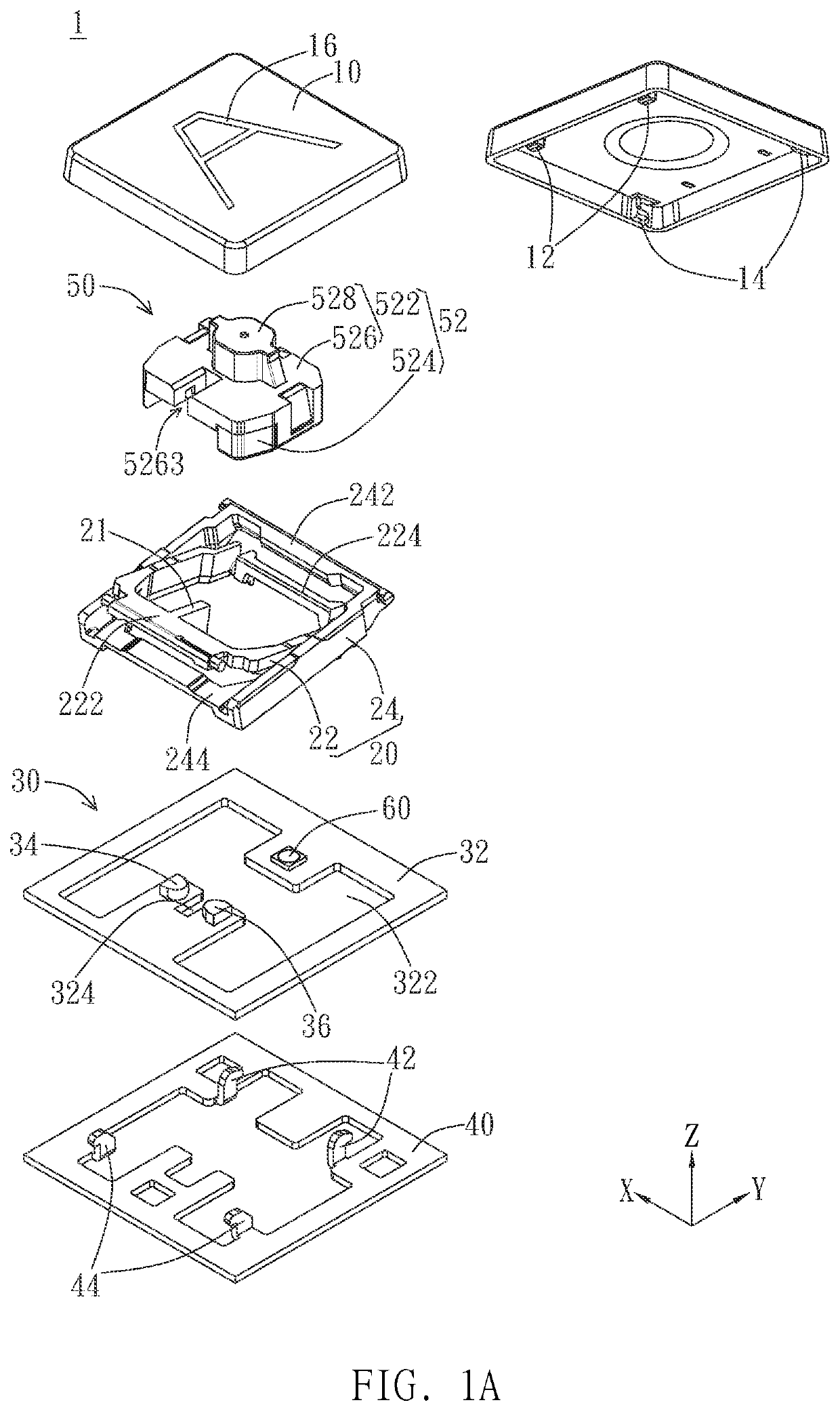
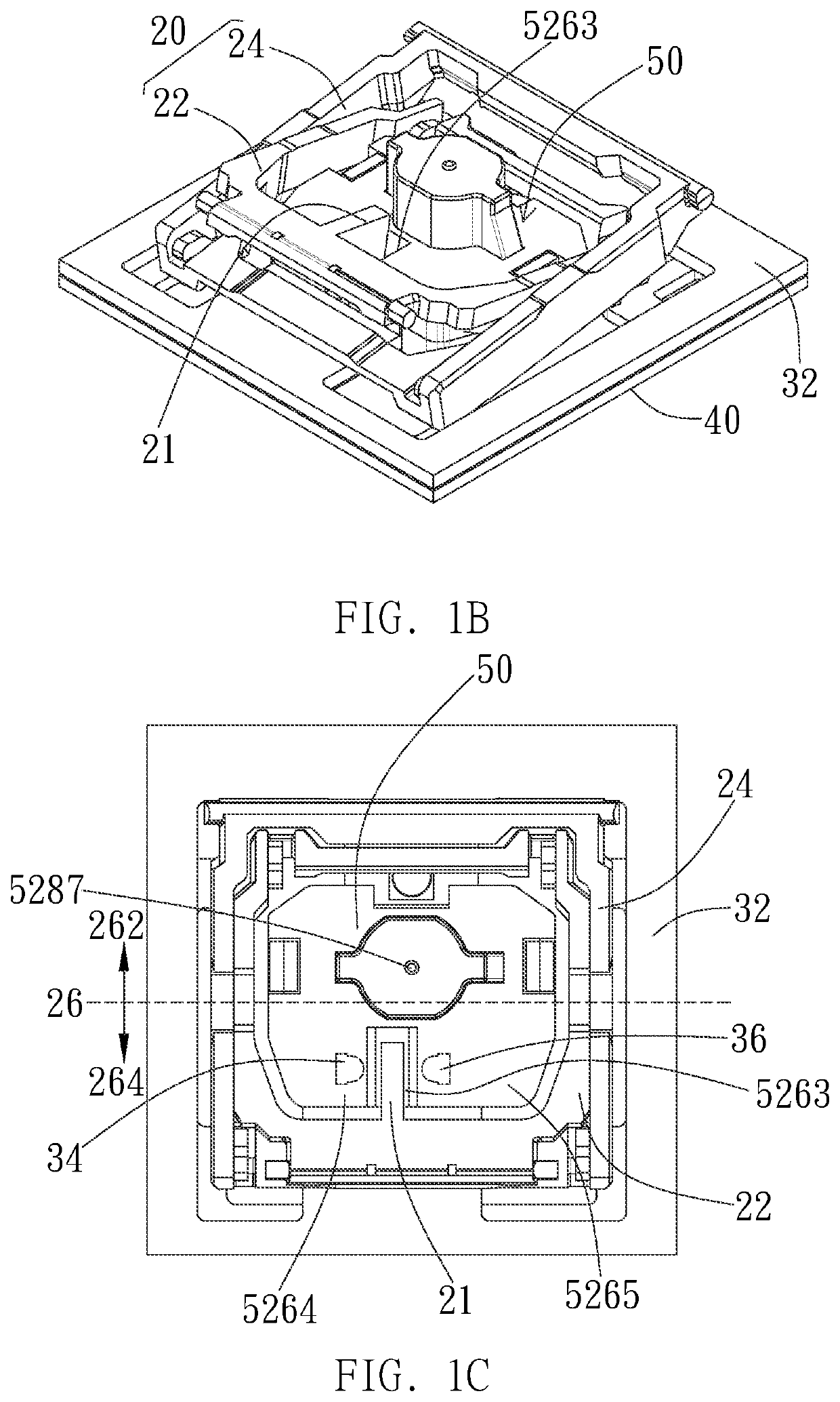
[0117]Referring to FIGS. 2A to 4B, the operation of the optical keyswitch of the first embodiment will be illustrated. FIGS. 2A, 3A, and 4A are cross-sectional views of the optical keyswitch along the X axis at the non-pressed position, the triggering position, and the lowest position, respectively. FIGS. 2B, 3B, and 4B are cross-sectional views of the optical keyswitch along the Y axis at the non-pressed position, the triggering position, and the lowest position, respectively. As shown in FIGS. 2A and 2B, the casing 52 has an up-down path 52a, and the sidewall 5266 is located between the up-down path 52a and the accommodation space 521 to separate the up-down path 52a from the accommodation space 521. In other words, the up-down path 52a is located within the open region 5263. In this embodiment, the emitter 34, the intensity adjustment space 52b, and the receiver 36 are preferably arranged sequentially along a straight optical path (e.g. arranged straightly along the X axis), and ...
second embodiment
[0123]Referring to FIGS. 6A to 8B, the operation of the optical keyswitch of the second embodiment will be illustrated. FIGS. 6A, 7A, and 8A are cross-sectional views of the optical keyswitch along the X axis at the non-pressed position, the triggering position, and the lowest position, respectively. FIGS. 6B, 6B, and 6B are cross-sectional views of the optical keyswitch along the Y axis at the non-pressed position, the triggering position, and the lowest position, respectively. As shown in FIGS. 6A and 6B, the casing 52 has the up-down path 52a, and the sidewall 5266 is located between the up-down path 52a and the accommodation space 521 to separate the up-down path 52a from the accommodation space 521. In other words, the up-down path 52a is located within the open region 5263. In this embodiment, the emitter 34, the intensity adjustment space 52b, and the receiver 36 are preferably arranged sequentially along a straight optical path (e.g. arranged straightly along the X axis), an...
fourth embodiment
[0133]Referring to FIGS. 13A to 14B, the operation of the optical keyswitch 4 of the fourth embodiment will be illustrated. FIGS. 13A and 14A are cross-sectional views of the optical keyswitch along the X axis at the non-pressed position and the triggering position, respectively. FIGS. 13B and 13B are cross-sectional views of the optical keyswitch along the Y axis at the non-pressed position and the triggering position, respectively. As shown in FIGS. 13A and 13B, when the keycap 10″ is not pressed, the protrusion 111′ of the keycap 10″ is located correspondingly above the deformable portion 5245. The horizontal surface 1112 of the protrusion 111′ is preferably parallel to the horizontal portion 5245b of the deformable portion 5245, and the sloped surface 1111 inclines upward from the horizontal surface 1112 toward the sidewall 5266, so that the vertical projection of the sloped surface 1111 on the deformable portion 5245 overlaps the deformable portion 5245. The protrusion 111′ and...
PUM
 Abstract
Description
Claims
Application Information
 - R&D
- Intellectual Property
- Life Sciences
- Materials
- Tech Scout
- Unparalleled Data Quality
- Higher Quality Content
- 60% Fewer Hallucinations
Browse by: Latest US Patents, China's latest patents, Technical Efficacy Thesaurus, Application Domain, Technology Topic, Popular Technical Reports.
© 2025 PatSnap. All rights reserved.Legal|Privacy policy|Modern Slavery Act Transparency Statement|Sitemap|About US| Contact US: help@patsnap.com


