Plasticizing device for a molding machine

a molding machine and plasticizing screw technology, applied in the field of plasticizing devices for molding machines, can solve the problems of plasticizing screw wear that cannot be deduced without, the function section is no longer visible for the user, etc., and achieve the effect of improving plasticizing

Pending Publication Date: 2021-11-18
ENGEL AUSTRIA
View PDF1 Cites 0 Cited by
  • Summary
  • Abstract
  • Description
  • Claims
  • Application Information

AI Technical Summary

Benefits of technology

[0004]The object of the present invention, thus, is to provide an improved plasticizing device compared to the prior art. In particular, the known disadvantages shall be avoided. Especially, a possibility for an improved analysis shall be provided without the necessity of dismounting the plasticizing screw.

Problems solved by technology

It is disadvantageous that the functioning section is no longer visible for the user after the assembly of the plasticizing device.
With this system, however, only the wear of the plasticizing screw can be deduced without having a direct view into the inside of the plasticizing cylinder.

Method used


Image

  • Plasticizing device for a molding machine
  • Plasticizing device for a molding machine
  • Plasticizing device for a molding machine

Examples


Embodiment Construction

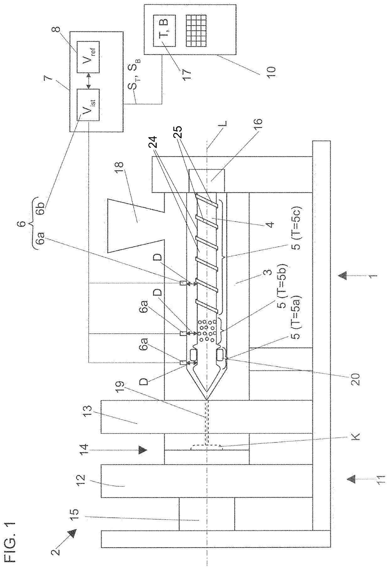
[0047]In FIG. 1, a molding machine 2 is illustrated in a schematic side view. This molding machine 2 comprises a closing unit 11 (illustrated on the left side). This closing unit 11 comprises a movable mold mounting plate 12, a stationary mold mounting plate 13, a mold tool 14 mounted to the mold mounting plates 12 and 13 and a drive device 15 (for example in the form of a toggle lever system) for the movable mold mounting plate 12. At least one cavity K is formed in the closed mold tool 14.

[0048]The molding machine 2 comprises a plasticizing device 1 (illustrated on the right side). This plasticizing device 1 comprises a plasticizing cylinder 3 and a plasticizing screw 4 which is arranged in the plasticizing cylinder 3, the plasticizing screw 4 being rotatable about a longitudinal axis L and being linearly movable along the longitudinal axis L. The plasticizing screw 4 is driven by a—for example electromotive—drive device 16. By means of the feed hopper 18 plastic material, prefera...


PUM

PropertyMeasurementUnit
distanceaaaaaaaaaa
circumferenceaaaaaaaaaa
movementsaaaaaaaaaa

Abstract

A plasticizing device includes a plasticizing cylinder and a plasticizing screw arranged in the plasticizing cylinder. The plasticizing screw is rotatable about, and linearly movable along, a longitudinal axis. The plasticizing screw comprises a functioning section. A sensor is arranged in or on the plasticizing cylinder, and a distance to the surface of the functioning section of the plasticizing screw can be measured by the sensor. A detecting device can detect a type of the functioning section and/or an operating state of the functioning section, can detect a distance signal progression by a movement of the functioning section relative to the sensor, can compare the detected distance signal progression with a stored distance signal progression, and can issue a signal representing the type of functioning section and/or the operating state of the functioning section depending on a matching of the detected distance signal progression with a stored distance signal progression.

Description

BACKGROUND OF THE INVENTION[0001]The present invention concerns a plasticizing device for a molding machine, in particular for an injection molding machine or an injection press, comprising a plasticizing cylinder, a plasticizing screw which is arranged in the plasticizing cylinder, the plasticizing screw being rotatable about a longitudinal axis and being linearly movable along the longitudinal axis. The plasticizing screw comprises at least one functioning section, and a sensor which is arranged in or on the plasticizing cylinder. A distance to the surface of the at least one functioning section of the plasticizing screw can be measured by the sensor. Moreover, the present invention concerns a molding machine comprising such a plasticizing device and a method for operating a plasticizing device.[0002]Different functioning sections are used in the molding process depending on the demands. For example, a functioning section can be a return flow shut-off device, a screw flight zone o...

Claims


Application Information

Patent Timeline
Patent Type & Authority Applications(United States)
IPC IPC(8): B29C45/76B29C45/50
CPCB29C45/76B29C45/50B29C2945/76665B29C2945/76187B29C2945/76096B29C45/52B29C45/80B29C45/768B29C2945/76193B29C2945/76939
Inventor ZEIDLHOFER, HERBERTKLAMMER, GUENTHER
Owner ENGEL AUSTRIA
Why Eureka
Try Eureka