
Intake centre fairing for a gas turbine engine

Active Publication Date: 2021-11-18
ROLLS ROYCE PLC
View PDF0 Cites 0 Cited by
  • Summary
  • Abstract
  • Description
  • Claims
  • Application Information

AI Technical Summary

Benefits of technology

The present invention provides an improved intake center fairing for gas turbine engines. This fairing provides greater control over the distribution of air flow and helps to reduce flow non-uniformities. It can be used in engines with short air intakes or in large engines with a high bypass ratio. Additionally, the fairing may be used to vent heat generated by the engine and to provide anti-icing to the fairing. Overall, the intake center fairing improves the performance and efficiency of gas turbine engines by optimizing the distribution of air flow.

Problems solved by technology

For large podded engines, length of air intakes is reduced which results in short intake design relative to the conventional intake designs.
The gas turbine engines with short intakes may face difficulty to achieve the required performance by the intake aero lines and the associated area distributions.
Conventional intake centre fairings in the form of axisymmetric rotating spinners used in such embedded engines and engines with short intake designs may fail to provide an optimal area distribution of air flow.

Method used


Image

  • Intake centre fairing for a gas turbine engine
  • Intake centre fairing for a gas turbine engine
  • Intake centre fairing for a gas turbine engine

Examples


Embodiment Construction

[0036]Aspects and embodiments of the present disclosure will now be discussed with reference to the accompanying figures. Further aspects and embodiments will be apparent to those skilled in the art.

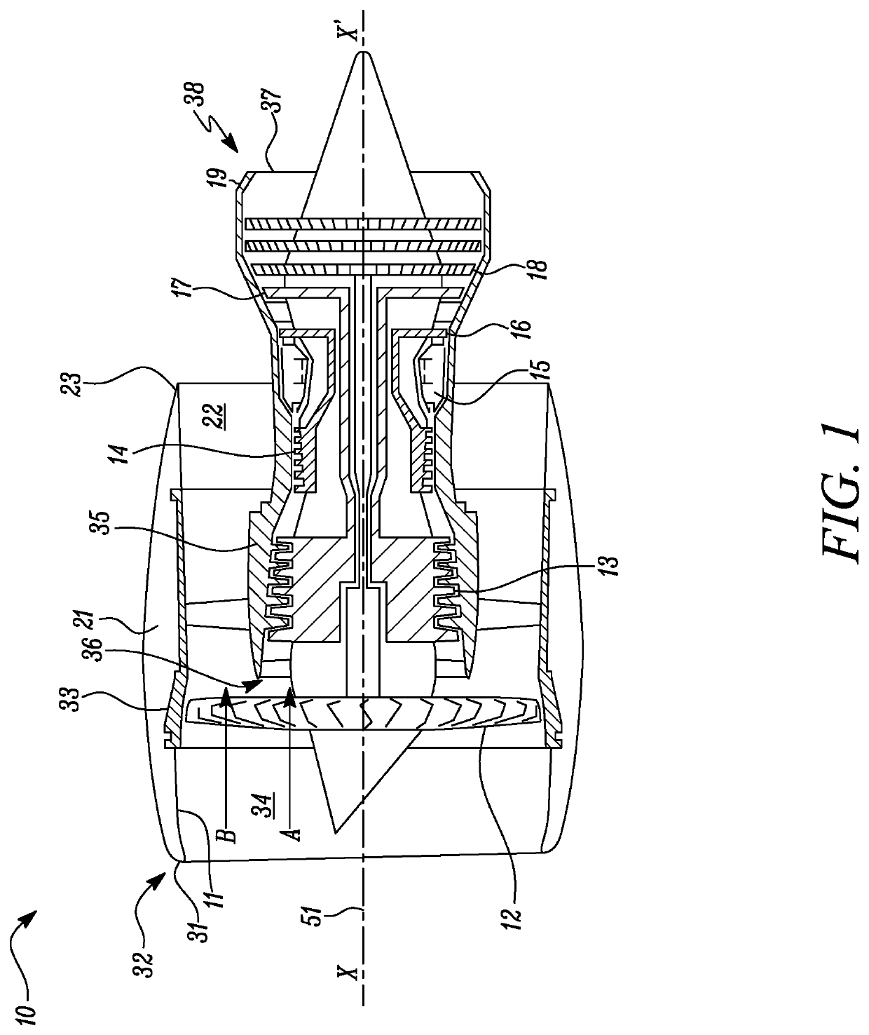
[0037]FIG. 1 shows a ducted gas turbine engine 10 having a principal rotational axis X-X′. The principal rotational axis X-X′ coincides with a longitudinal centre line 51 of the gas turbine engine 10.

[0038]In the following disclosure, the following definitions are adopted. The terms “upstream” and “downstream” are considered to be relative to an air flow through gas turbine engines. The terms “axial” and “axially” are considered to relate to the direction of a principal rotational axis of the gas turbine engines.

[0039]In the following disclosure, the term longitudinal axis is defined as an axis along the direction of the principal rotational axis of the gas turbine engines. The term horizontal axis is defined as an axis normal to the longitudinal axis. The term transverse axis is defined...


PUM


Abstract

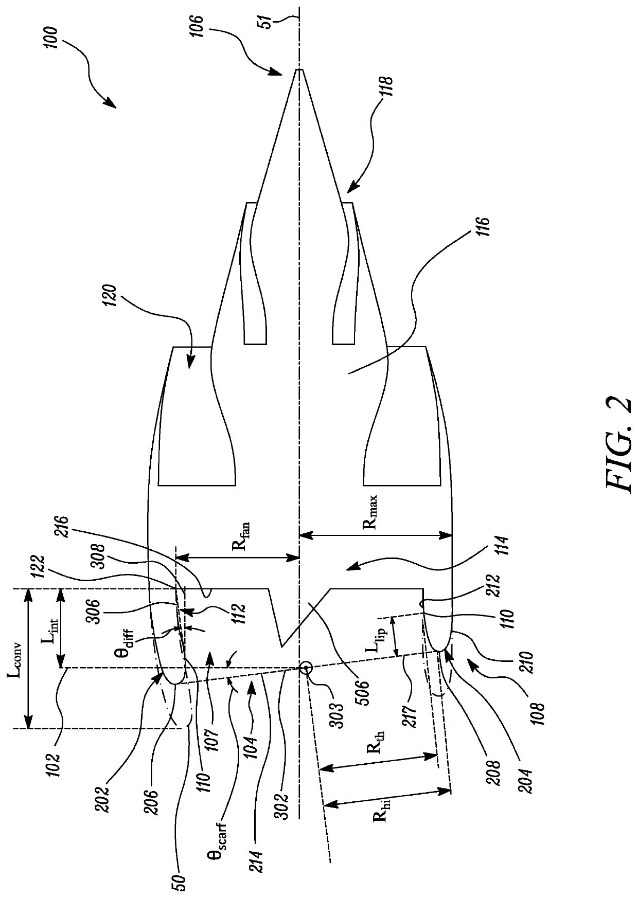
An intake centre fairing for a gas turbine engine includes a body. The body includes an outer surface, an apex point and a base. The apex point is at a first end of the body and the base is at a second end of the body. The base includes a base centre. The body defines a longitudinal axis along its length, a radial direction relative to the longitudinal axis and a circumferential direction relative to the longitudinal axis. The outer surface of the body is tapered from the base to the apex point along the longitudinal axis. The apex point is radially offset relative to the base centre along the radial direction. The apex point is further circumferentially offset relative to the base centre along the circumferential direction.

Description

CROSS-REFERENCE TO RELATED APPLICATIONS[0001]This specification is based upon and claims the benefit of priority from United Kingdom patent application number GB 2007186.6 filed on May 15, 2020, the entire contents of which is incorporated herein by reference.BACKGROUNDTechnical Field of the Disclosure[0002]The present disclosure relates to an intake centre fairing, and in particular to an intake centre fairing for a gas turbine engine for powering aircraft.Description of the Related Art[0003]An embedded gas turbine engine generally has a closed coupling between an engine fan and an upstream intake duct. This configuration can either work without an inlet guide vane (IGV) or with an IGV. The gas turbine engine typically also has an intake centre fairing that rotates with the fan and is called a spinner. Conventionally, the spinner is axisymmetric. In case of embedded gas turbine engines, the intake centre fairing in the form of a spinner and the outer geometry of the duct controls a...

Claims


Application Information

Patent Timeline
IPC IPC(8): F02C7/04
CPCF02C7/04F05D2240/12F05D2220/323F05D2250/292F05D2250/312B64C11/14
Inventor CHRISTIE, ROBERT EMACMANUS, DAVID G
Owner ROLLS ROYCE PLC
Learn More