
Vehicle sensor mounting structure and vehicle sensor bracket set

a technology for vehicle sensors and mounting structures, which is applied in the direction of vehicle components, instruments, measurement devices, etc., can solve the problems of reduced sensor accuracy, reduced sensor accuracy, and deterioration of vehicle aerodynamic performance, and achieve high accuracy

Pending Publication Date: 2021-11-25
TOYOTA JIDOSHA KK
View PDF1 Cites 1 Cited by
  • Summary
  • Abstract
  • Description
  • Claims
  • Application Information

AI Technical Summary

Benefits of technology

The present patent is about a vehicle sensor mounting structure and a bracket set for mounting sensors on a vehicle roof. The structure and bracket set are designed to reduce blind spots of sensors in the vehicle front-rear direction without raising the mounting positions of the sensors. By fitting and fixing a sensor kit onto a bracket, the mutual positional relationships of the sensors can be maintained with high accuracy. This improves the accuracy of various vehicle controls and reduces mounting man-hours and design man-hours. The bracket set includes a first bracket and a second bracket that can be easily mounted on the roof and can be diverted to different types of vehicles. Overall, the structure and bracket set provide a more efficient and accurate vehicle sensor mounting solution.

Problems solved by technology

However, when the sensors are gathered in the center of the roof of the vehicle, blind spots of the sensors tend to occur due to the roof end in the front-rear direction of the vehicle.
In this case, when the mounting positions of the sensors are raised to reduce the blind spots of the sensors in the front-rear direction of the vehicle, the aerodynamic performance of the vehicle is deteriorated and the rigidity of the mounting portions of the sensors is lowered, which may cause a decrease in sensor accuracy due to vibration or wind during traveling.

Method used


Image

  • Vehicle sensor mounting structure and vehicle sensor bracket set
  • Vehicle sensor mounting structure and vehicle sensor bracket set
  • Vehicle sensor mounting structure and vehicle sensor bracket set

Examples


Embodiment Construction

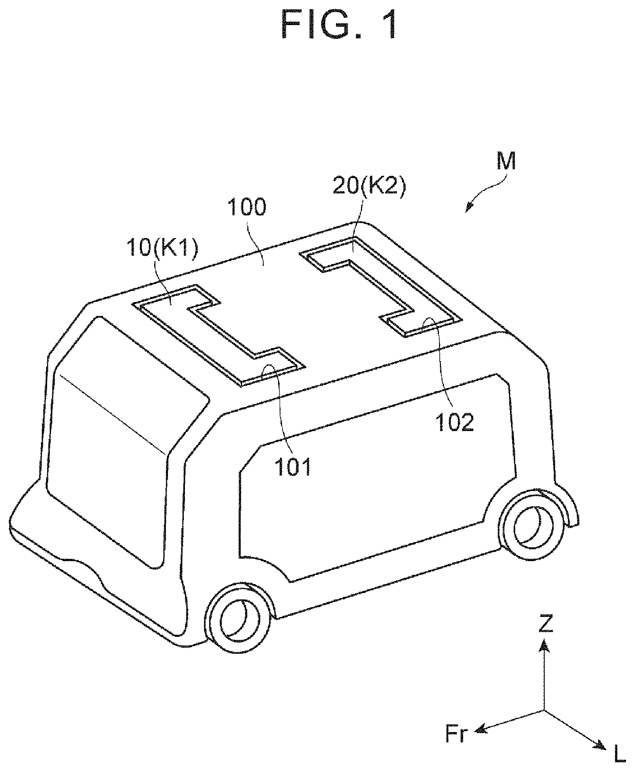
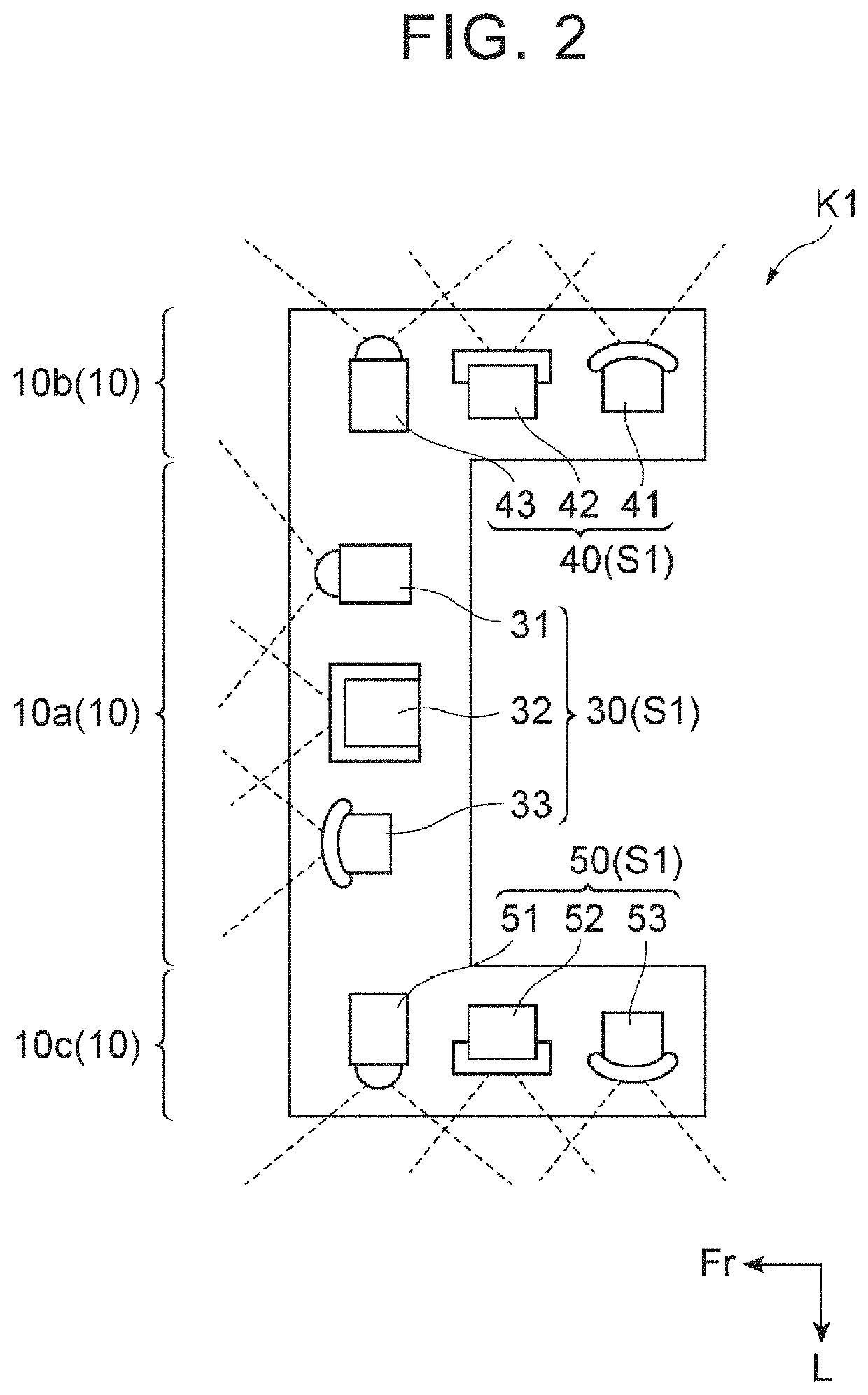
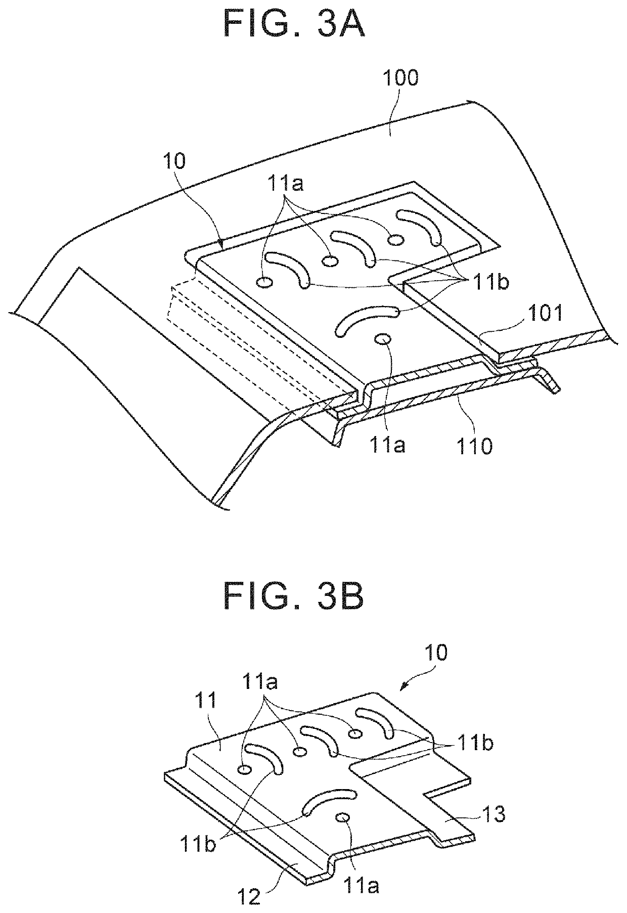
[0029]Hereinafter, an embodiment of the present disclosure will be described with reference to the drawings. A vehicle sensor mounting structure in the present disclosure is a mounting structure for sensors mounted on a roof of a vehicle to detect the external environment of the vehicle. The type of the vehicle and the shape of the roof are not particularly limited. The external environment includes, for example, the situation of other vehicles around the vehicle.

[0030]FIG. 1 is a perspective view of an entire vehicle for illustrating a vehicle sensor mounting structure according to the embodiment. In FIG. 1, the illustration of the sensors is omitted. In each figure, a three-dimensional orthogonal coordinate system is shown in which the front direction of a vehicle M is indicated as Fr, the left direction of the vehicle M is indicated as L, and the upward direction of the vehicle M is indicated as Z.

[0031]The vehicle M shown in FIG. 1 is, for example, an autonomous driving vehicle ...


PUM


Abstract

A vehicle sensor mounting structure includes a first sensor kit and a second sensor kit, each having a sensor group including a plurality of sensors and a bracket on an upper surface of which the sensor group is installed, a first fitting portion which is provided on a front side of the roof in a vehicle front-rear direction and into which a first bracket is fitted such that the upper surface is exposed, and a second fitting portion which is provided on a rear side of the roof in the vehicle front-rear direction so as to face the first fitting portion in the vehicle front-rear direction and into which a second bracket is fitted such that the upper surface is exposed. The plurality of sensors of each sensor group includes at least two kinds of sensors selected from among a camera, a millimeter wave radar, and a LiDAR sensor.

Description

CROSS-REFERENCE TO RELATED APPLICATION[0001]This application claims priority to Japanese Patent Application No. 2020-088158 filed on May 20, 2020, incorporated herein by reference in its entirety.BACKGROUND1. Technical Field[0002]The present disclosure relates to a vehicle sensor mounting structure and a vehicle sensor bracket set.2. Description of Related Art[0003]US 2016-0334790 A is known as a technical document relating to a vehicle sensor mounting structure. This publication describes a structure in which sensors are integrally arranged in the center of a roof of a vehicle.SUMMARY[0004]However, when the sensors are gathered in the center of the roof of the vehicle, blind spots of the sensors tend to occur due to the roof end in the front-rear direction of the vehicle. In this case, when the mounting positions of the sensors are raised to reduce the blind spots of the sensors in the front-rear direction of the vehicle, the aerodynamic performance of the vehicle is deteriorated a...

Claims


Application Information

Patent Timeline
IPC IPC(8): G01S13/931G01S13/86B60R11/00
CPCG01S13/931G01S13/86B60R2011/004G01S2013/9327B60R11/00B60R2011/0042G01S7/027
Inventor HASEGAWA, TAROHIGASHIMACHI, NAOYA
Owner TOYOTA JIDOSHA KK
Learn More