Post-Process Apparatus and Control Method
- Summary
- Abstract
- Description
- Claims
- Application Information
AI Technical Summary
Benefits of technology
Problems solved by technology
Method used
Image

Examples
first example
f1. FIRST EXAMPLE
[0118]The manual stapling process during the punching process will be described with reference to FIGS. 7A to 7D.
[0119]Signals shown in FIGS. 7A to 7D are extraction of main inputs and outputs associated with the punching process (operation) and the manual stapling process (operation).
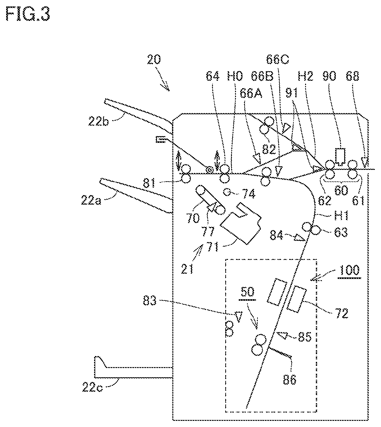
[0120]A signal (a) from pre-registration sensor 68 that senses a sheet conveyed from image forming apparatus 10 for determining timing of a punching operation and a signal (d) from sheet sensor 511 that senses insertion of a sheet for manual stapling are shown as input signals.
[0121]A signal (b) for paper stop roller drive motor 542 that drives paper stop roller 61 that conveys a sheet in punching process portion 90, a signal (c) for punch drive motor 546 that performs a punching operation, and a signal (e) for stapler drive motor 549 that operates the stapler are shown as output signals. “To operate the stapler” means putting a staple into a sheet.
[0122]FIG. 7A is a timing chart showi...
second example
f2. SECOND EXAMPLE
[0136]The manual stapling process during the up-and-down operation by exit tray 22a will be described with reference to FIGS. 8A to 8C.
[0137]Signals shown in FIGS. 8A to 8C are extraction of main inputs and outputs associated with an up-and-down movement process (operation) of exit tray 22a and the manual stapling process (operation).
[0138]A signal (g) from process tray sheet sensor 77 (FIG. 3), a signal (h) from tray upper surface sensor 512 (see FIG. 5), and the (d) signal from sheet sensor 511 are shown as input signals. A signal (i) for tray drive motor 541 for the up-and-down operation by exit tray 22a and a signal (e) for stapler drive motor 549 that operates the stapler are shown as output signals.
[0139]FIG. 8A is a timing chart showing an example in which timing to drive tray drive motor 541 coincides with timing to drive stapler drive motor 549 when the manual stapling process is performed based on insertion of a sheet into sheet insertion port 21a (see FI...
third example
f3. THIRD EXAMPLE
[0149]Relation between a saddle stitch and center fold process and the manual stapling process will be described with reference to FIGS. 9A to 9C.
[0150]Signals shown in FIGS. 9A to 9C are extraction of main inputs and outputs associated with the saddle stitch and center fold process (operation) and the manual stapling process (operation).
[0151]A signal (j) from saddle carry-in portion sensor 84, a signal (k) from saddle process tray sensor 85, a signal (l) from ejection sensor 83, and the signal (d) from sheet sensor 511 are shown as input signals. A signal (m) for saddle stitch drive motor 551, a signal (n) for folding knife drive motor 547, a signal (o) for folding roller drive motor 550, and the signal (e) for stapler drive motor 549 are shown as output signals.
[0152]FIG. 9A is a timing chart showing an example in which timing to drive folding roller drive motor 550 during a center fold operation coincides with timing to drive stapler drive motor 549.
[0153]Referr...
PUM
 Abstract
Description
Claims
Application Information
 - Generate Ideas
- Intellectual Property
- Life Sciences
- Materials
- Tech Scout
- Unparalleled Data Quality
- Higher Quality Content
- 60% Fewer Hallucinations
Browse by: Latest US Patents, China's latest patents, Technical Efficacy Thesaurus, Application Domain, Technology Topic, Popular Technical Reports.
© 2025 PatSnap. All rights reserved.Legal|Privacy policy|Modern Slavery Act Transparency Statement|Sitemap|About US| Contact US: help@patsnap.com