Method For Determining the Start of Relaxation After a Burn-In Process at Optical Display Devices Controllable Pixel by Pixel

a technology of optical display device and burn-in process, which is applied in the direction of radio frequency controlled devices, instruments, television systems, etc., can solve the problems of delay not precisely known or only determined, and the burn-in behavior of other displays and projecting display devices working by other physical principles, and achieves long service time, high importance, and high rate

Active Publication Date: 2021-12-09
TECHNOTEAM HLDG GMBH
View PDF5 Cites 1 Cited by
  • Summary
  • Abstract
  • Description
  • Claims
  • Application Information

AI Technical Summary

Benefits of technology

[0067]Displays applied in vehicles are used over a particularly long service time and at a particularly high rate to present graphics or images which are static or unchanged over a long time. Thus, the exact and reliable determination of interferences caused by such static images is of particularly high importance here. Based on a more precise determination of the start of relaxation, the proposed method allows for a more reliable assessment of displays than methods known in the art.

Problems solved by technology

Likewise, displays and projecting display devices based on DMD (digital mirror device) technology are known to show burn-in behavior.
Likewise, other displays and projecting display devices working by other physical principles may be affected by such burn-in behavior.
Typically, this delay is not precisely known or may only be determined with additional effort.
Moreover, the point in time, at which a recording may be triggered at a luminance density measurement camera, is generally not synchronous to the switchover of the presented image but subject to a fluctuating deviation (jitter).
Because of the switchover delay which is not exactly known and because of the jitter there is the risk on the one hand to trigger a recording of a camera image at the luminance density measurement camera already prior to switching over the presented burn-in image to the test image.
On the other hand, there is the risk for late triggering of the luminance density measurement camera relative to the switchover of the display device.
This way, the burn in effect will be underestimated.
Likewise, methods, in which only a subarea of the sensor field of the camera referred to as area of interest (AOI) or a plurality of such subareas are read out, are possible and result in a significant increase of the trigger clock rate.

Method used


Image

  • Method For Determining the Start of Relaxation After a Burn-In Process at Optical Display Devices Controllable Pixel by Pixel
  • Method For Determining the Start of Relaxation After a Burn-In Process at Optical Display Devices Controllable Pixel by Pixel
  • Method For Determining the Start of Relaxation After a Burn-In Process at Optical Display Devices Controllable Pixel by Pixel

Examples


Embodiment Construction

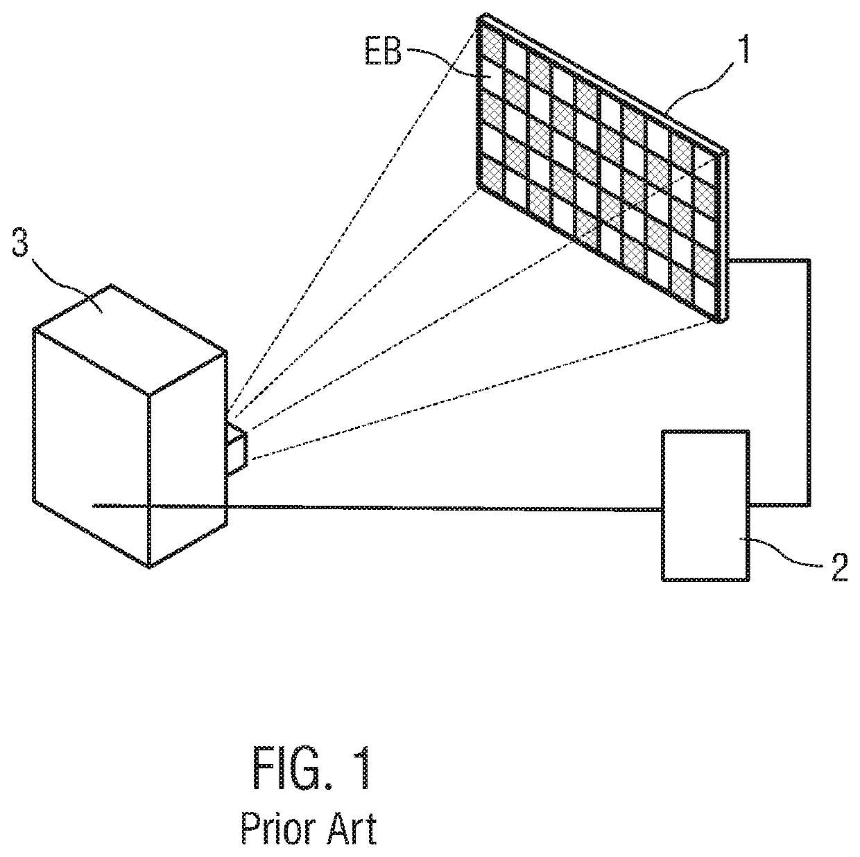
[0075]FIG. 1 is a schematic view of a measurement setup known in the art for charting the burn-in behavior of a display 1. The measurement setup comprises a computer 2 connected to the display 1 and to a camera 3.

[0076]The display 1 to be charted may for example be a liquid crystal display (LCD) or an organic luminous display (OLED organic light emitting diode).

[0077]The computer 2 is configured to output images or graphics on the display 1. Instead of the computer 2, a test image generator not shown in detail may be used to output images on the display 1.

[0078]A burn-in image EB being output on the display 1 is presently illustrated. The burn-in image EG is configured as a chessboard pattern with square fields distributed across the entire image area. The square fields have an approximately homogenous luminance density, wherein adjacent fields differ from one another in luminance density. In an embodiment, the chessboard pattern consists of fields with a maximized difference in con...


PUM


Abstract

The invention relates to a method for determining a start of relaxation (tR) when switching over an optical display device (1) controllable pixel by pixel from a burn-in image (EB′) to a relaxation image (RB), wherein. A trigger image area (TB) having at least one image pixel is set to pixel values such that a parameter determined based on the at least one pixel value across the trigger image area (TB) differs between the burn-in image (EB′) and the relaxation image (RB). The local distribution of a greyscale value is continuously recorded by means of a camera (3, 13). A trigger subfield (20) comprising at least one sensor pixel (15) is defined matching the trigger image area (TB). A trigger parameter (T) is continuously determined from the pixel values of the at least one sensor pixel (15) in the trigger subfield (20) with a trigger clock rate and the start of relaxation (tR) is determined as the point in time at which the continuously determined trigger parameter (T) crosses the trigger threshold value (TS). The invention furthermore relates to a device and a method for determining the burn-in behavior of a display device (1) as well as the use of such a method for a display (1) determined for application in a vehicle.

Description

CROSS-REFERENCE TO RELATED APPLICATION[0001]This application claims priority to German patent application no. 10 2020 207 184.5 filed on Jun. 9, 2020, which is hereby incorporated by reference in its entirety.BACKGROUND1. Field of Invention[0002]The invention relates to a method for determining the start of relaxation after at an optical display device controllable pixel by pixel having been subjected to a burn-in process. Moreover, the invention relates to a method and a device for determining the burn-in behavior at such a display device as well as to the use of such a method for determining the burn-in behavior of displays applied in vehicles.2. Background Art[0003]Optical display devices electronically controllable pixel by pixel, in particular displays, may show changes of a presented image referred to as burn-in. Burn-in may be caused by prolonged invariant presentation of an image on the display device. If, immediately after having presented such a burned-in image, the displa...

Claims


Application Information

Patent Timeline
Patent Type & Authority Applications(United States)
IPC IPC(8): G06K9/46G06K9/78
CPCG06K9/4661G06K9/4652G06K9/78H04N17/00H04N25/70G09G3/20G09G3/36G09G3/32G09G2320/046G09G2320/0693G09G2320/0257G09G2380/10G09G3/006G06T7/20H01L27/146G09G2320/0271G09G2320/0276H04N17/02G06V10/56G06V10/10G06V10/60
Inventor KRÜGER, UDOROTSCHOLL, INGOPOSCHMANN, RALFPORSCH, TOBIAS
Owner TECHNOTEAM HLDG GMBH
Why Eureka
Try Eureka