Filter with combined wear indication and pull tab

a filter and pull tab technology, applied in the field of filters, can solve the problems of difficulty in visualizing the saturation level of contaminant particles in the filter and the need for replacement, and achieve the effect of facilitating visual determination and difference in contaminant saturation level

Pending Publication Date: 2021-12-16
KONINKLJIJKE PHILIPS NV
View PDF0 Cites 0 Cited by
  • Summary
  • Abstract
  • Description
  • Claims
  • Application Information

AI Technical Summary

Benefits of technology

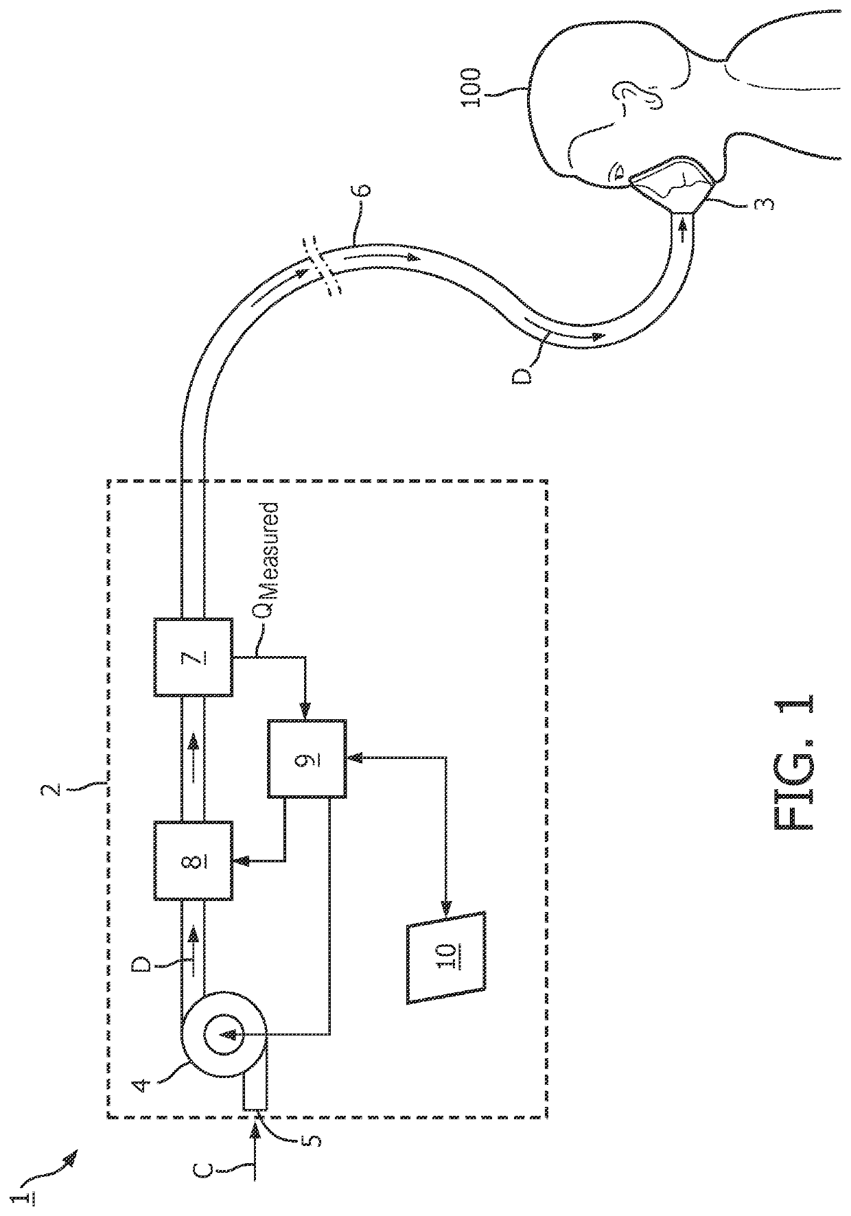
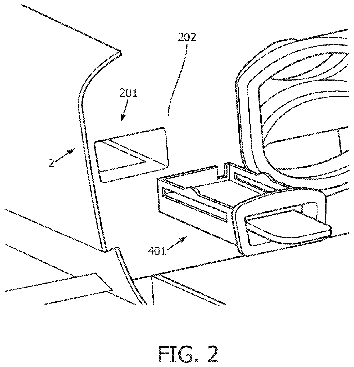
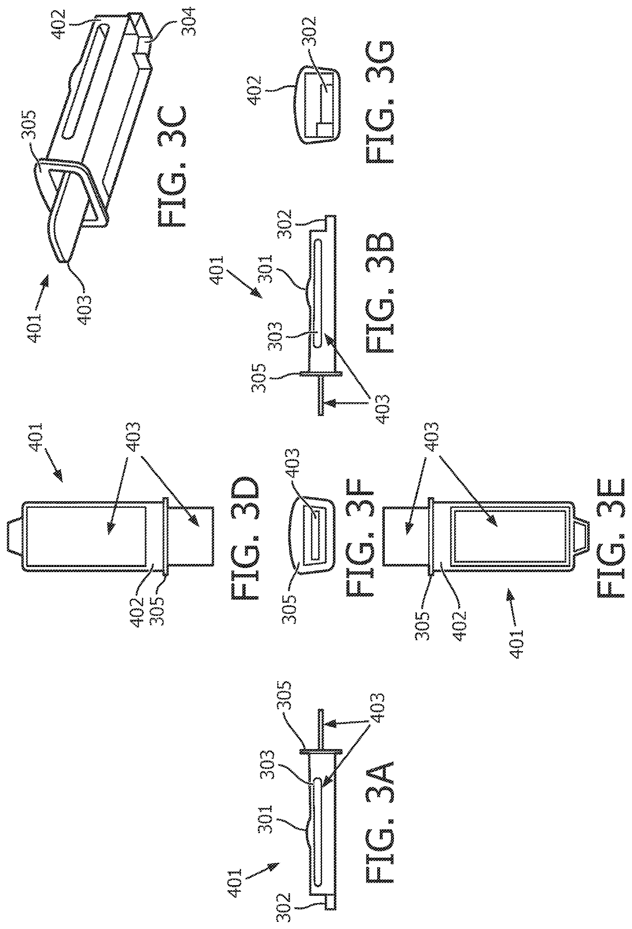
[0008]Accordingly, one or more embodiments provide a filter assembly configured to facilitate ease in visually determining when a filter media for a pressurized breathing gas system needs to be changed, by using one section of the filter media to filter a flow of incoming air to the system and isolating another non-filtering section of the media from the flow of incoming air, such that a difference in the contaminant saturation level of the filtering section compared to the non-filtering section is apparent. In one embodiment, a filter assembly for filtering incoming air entering a pressurized breathing gas system includes a filter housing and a filter media. The filter media includes a filtering section and a non-filtering section. The filter housing is structured to be inserted within a pressure generating device used to generate a flow of pressurized air for delivery to an airway of a user of the pressurized breathing gas system. The filtering section is disposed within the filter housing. The non-filtering section is disposed outside of the filter housing. The filter housing comprises a filtering boundary structured to separate the non-filtering section from the filtering section such that the non-filtering section is isolated from the flow of incoming air. The filtering section and the non-filtering section are structured to be visually compared to one another such that a contaminant matter saturation level of the filter media can be determined.

Problems solved by technology

Visually determining when a filter is saturated with particulate matter and needs to be replaced can be difficult.

Method used


Image

  • Filter with combined wear indication and pull tab
  • Filter with combined wear indication and pull tab
  • Filter with combined wear indication and pull tab

Examples


Embodiment Construction

[0015]As used herein, the singular form of “a”, “an”, and “the” include plural references unless the context clearly dictates otherwise. As used herein, the statement that two or more parts or components are “coupled” shall mean that the parts are joined or operate together either directly or indirectly, i.e., through one or more intermediate parts or components, so long as a link occurs. As used herein, “directly coupled” means that two elements are directly in contact with each other.

[0016]As used herein, the word “unitary” means a component is created as a single piece or unit. That is, a component that includes pieces that are created separately and then coupled together as a unit is not a “unitary” component or body. As employed herein, the statement that two or more parts or components “engage” one another shall mean that the parts exert a force against one another either directly or through one or more intermediate parts or components. As employed herein, the term “number” sh...


PUM

PropertyMeasurementUnit
distanceaaaaaaaaaa
lengthaaaaaaaaaa
lengthaaaaaaaaaa

Abstract

A filter assembly for filtering a flow of incoming air entering a pressurized breathing gas system includes a filter housing and a filter media. The filter media includes a filtering section and a non-filtering section. The filter housing is structured to be inserted within a pressure generating device used in the pressurized breathing gas system. The filtering section is disposed within the filter housing and is structured to filter contaminant matter from the flow of incoming air. The non-filtering section is disposed outside of the housing and is structured to be separated from the filtering section so as to not make contact with the flow of incoming air. The filtering section and the non-filtering section are structured to be visually compared to one another such that a contaminant matter saturation level of the filter media can be determined.

Description

1. FIELD OF THE INVENTION[0001]The present invention pertains to pressurized breathing gas systems, and, more particularly, to filters used in pressurized breathing gas systems, and a method for determining when replacement of said filters is necessary.2. DESCRIPTION OF THE RELATED ART[0002]Many individuals suffer from disordered breathing during sleep. Sleep apnea is a common example of such sleep disordered breathing suffered by millions of people throughout the world. It is known to deliver positive airway pressure (PAP) to treat a medical disorder, such as chronic obstructive pulmonary disease (COPD) or sleep apnea syndrome, in particular, obstructive sleep apnea (OSA). Known PAP therapies include continuous positive airway pressure (CPAP), wherein a constant positive pressure is provided to the airway of the patient in order to splint open the patient's airway, and variable airway pressure, wherein the pressure provided to the airway of the patient is varied with the patient's ...

Claims


Application Information

Patent Timeline
Patent Type & Authority Applications(United States)
IPC IPC(8): A61M16/10A61M16/00A61M16/06
CPCA61M16/107A61M2016/003A61M16/06A61M16/0066B01D46/10B01D46/0006B01D46/0015B01D46/0086B01D46/4227B01D46/4254B01D2265/04B01D2271/025B01D2275/205A62B23/02A62B7/10A61M2205/7545A61M2205/7581A61M2205/583
Inventor DIMATTEO, MARK WILLIAMBARCLAY, MARK WAYNEANSWINE, MATTHEW SCOTT
Owner KONINKLJIJKE PHILIPS NV
Why Eureka
Try Eureka