Guardrail terminal barrier

Pending Publication Date: 2021-12-16
OHIO UNIV
View PDF0 Cites 1 Cited by
  • Summary
  • Abstract
  • Description
  • Claims
  • Application Information

AI Technical Summary

Benefits of technology

[0007]The focus of the present invention is to provide a safer and more efficient solution to roadside guardrail terminal ends. To that end, the pres

Problems solved by technology

The level of incompressibility and viscous effects of the fluid requires a sign

Method used


Image

  • Guardrail terminal barrier
  • Guardrail terminal barrier
  • Guardrail terminal barrier

Examples


Example

Example

[0043]The following experiment demonstrated the efficiency of the present invention. A horizontal impact tester accelerates a 4.4 kg sled up to 3 m / s providing impact energy up to 20 J. The apparatus was outfitted with an accelerometer to measure the acceleration pulse during the impact and high-speed camera to measure the displacement and velocity of the ram.

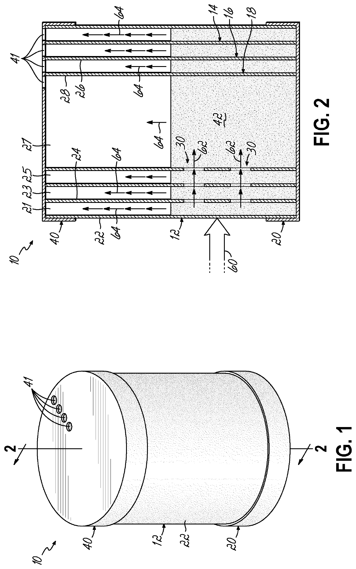
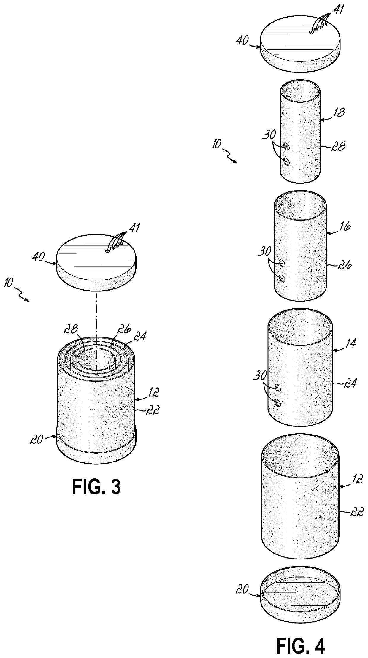
[0044]Test samples were constructed using 32 oz. plastic jars as the primary structure (4 in. diameter, 6.5 in. height) and smaller 8 oz. containers for the internal structures (2.25 in. diameter, 4.5 in. height). Orifices were placed on the internal structures to allow for fluid transport between the chambers. The placement of the orifices on the internal structures is shown. Testing criteria for the samples included: primary structure, primary structure with interior structure (no orifices), primary structure with interior structure (one orifice), primary structure with interior structure (two orifices), and primary st...


PUM


Abstract

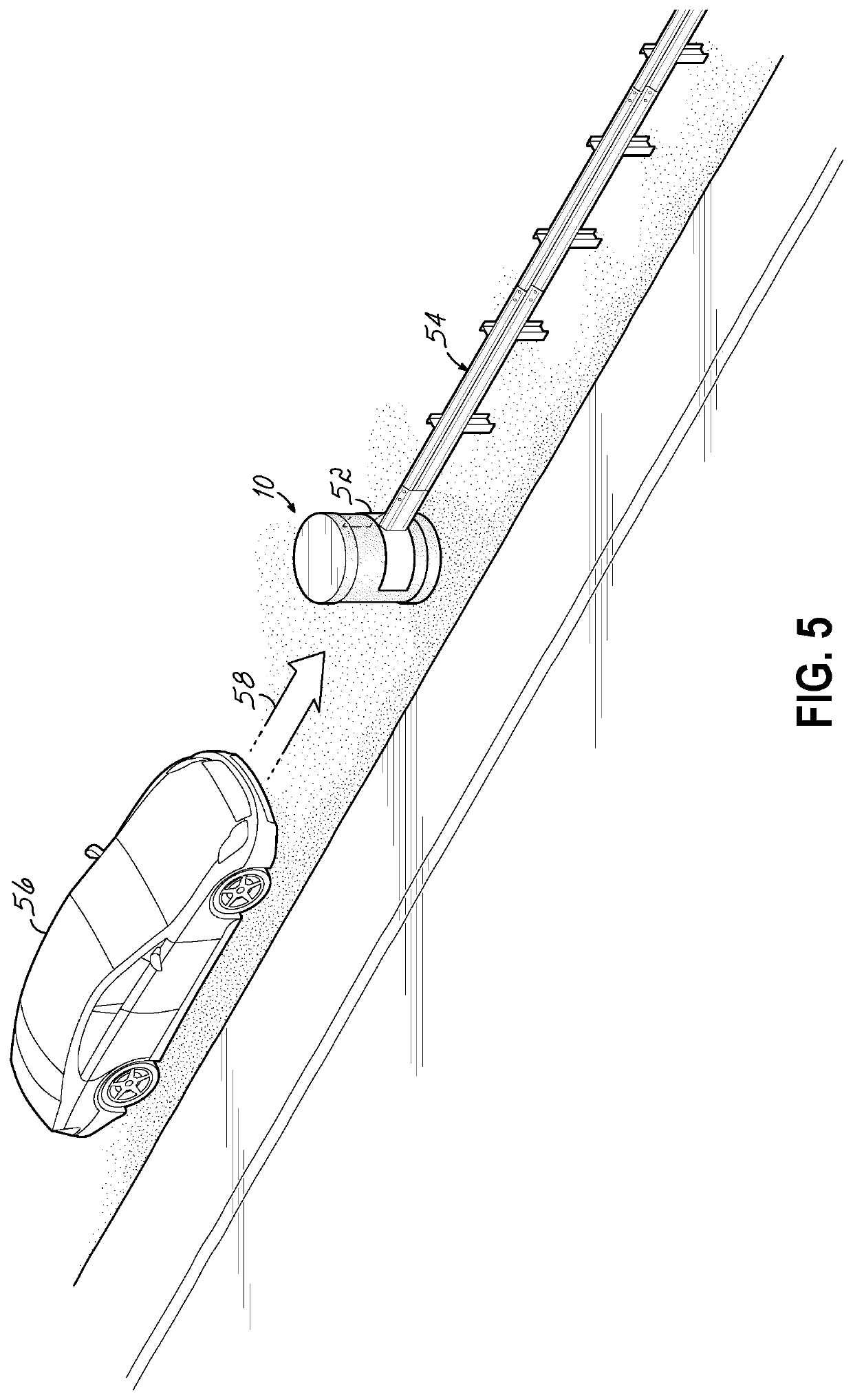
A force-absorbing barrier includes a plurality of chambers at least partially filled with fluid. The walls defining the chambers are flexible. Fluid passages in the interior walls between chambers allow fluid flow between the chambers. Alternatively, the chambers are filled with structures instead of or in addition to a fluid. The fluid flow from chamber to chamber and/or the deformation of the structures will absorb energy from the impact a motor vehicle, preventing the vehicle from impacting the terminal of a guardrail.

Description

CROSS-REFERENCE TO RELATED APPLICATIONS[0001]This application is a continuation-in-part of U.S. patent application Ser. No. 15 / 781,500, filed on Jun. 5, 2018 (and published as U.S. Patent Publication No. 2018 / 0266062 A1 on Sep. 20, 2018), which is a U.S. national phase filing of International Patent Application No. PCT / US2016 / 065587, filed on Dec. 8, 2016 (and published as International Publication No. WO 2017 / 100433 A1 on Jun. 15, 2017), which claims the benefit of U.S. Patent Application Ser. No. 62 / 265,050, filed on Dec. 9, 2015, the disclosures of all of which are incorporated by reference herein in their entireties.BACKGROUND OF THE INVENTION[0002]Automobile accidents are a common occurrence in daily driving activities. According to the National Highway Traffic Safety Administration (NHTSA), over 33,000 vehicle related fatalities were reported in 2012. With millions of vehicles on the road in the U.S. at any given time, improving transportation safety is always needed. Specific...

Claims


Application Information

Patent Timeline
IPC IPC(8): E01F15/14
CPCE01F15/146E01F15/143E01F15/141E01F15/145
Inventor ALI, MUHAMMADJENSON, SEAN R.ALAM, KHAIRUL
Owner OHIO UNIV
Why Eureka
Try Eureka