Eureka AIR delivers breakthrough ideas for toughest innovation challenges, trusted by R&D personnel around the world.

High-heeled shoe sole structure and high-heeled shoe including same

Pending Publication Date: 2021-12-23
KIM IL SOO
View PDF0 Cites 0 Cited by
  • Summary
  • Abstract
  • Description
  • Claims
  • Application Information

AI Technical Summary

Benefits of technology

The invention includes a shoe with a bending portion that improves stability when walking in heeled shoes. This bending portion helps to limit flexion of the metatarsophalangeal joint during a swing phase and maintain stability of the foot during a stance phase or standing. Additionally, the shoe has a bending portion at the rear of the metatarsophalangeal joint or a ground support boundary line that moves in the same direction as the metatarsophalangeal joint and the heel during heel off and toe-off while walking. This helps to walk comfortably and stably.

Problems solved by technology

A pedestrian wearing conventional high-heeled shoes suffers from an ankle sprain due to instability of a rearfoot depending on a high heel, when a body's weight is loaded on the ground while standing or walking.
Particularly, when a platform is attached to a sole of the front portion of the high-heeled shoe supported by the ground, movement of the forefoot and rearfoot is not allowed at all.
However, since the conventional high heel sole structure is not flexible, it cannot cope with this, and thus there is a problem in that the heel comes out of the shoe, so that it is difficult to normally walk.
However, even in this case, since it is not bent enough to follow the movement of the foot, and the heel comes out from the shoe as shown in FIG. 27 (c).
Therefore, since the high-heeled shoe to which the conventional sole structure S is applied is not suitable for the movement of the foot according to the walking, it is not possible to effectively support the foot.

Method used


Image

  • High-heeled shoe sole structure and high-heeled shoe including same
  • High-heeled shoe sole structure and high-heeled shoe including same
  • High-heeled shoe sole structure and high-heeled shoe including same

Examples


first embodiment

[0091]FIG. 10 illustrates a high-heeled shoe for explaining the present invention, and FIG. 11 illustrates an exploded view of main portions of the high-heeled shoe of FIG. 10.

[0092]The high-heeled shoe of the first embodiment of the present invention includes a foot fixing portion 1, an insole 3, a sole structure 5, an outsole 7, and a heel 9.

[0093]The foot fixing portion 1 is a portion that may wrap the foot, forms a shape of the shoe, and is made of leather, etc. In addition, the insole 3 is a portion that is in direct contact with the sole of the foot. The sole structure 5 may support a load of a pedestrian, and simultaneously, maintain a shape of the shoe. In addition, the insole 3 may be coupled to an upper side of the sole structure 5. The outsole 7 is coupled to a lower portion of the sole structure 5, and a front side thereof directly contacts the ground. The heel 9 is coupled to the sole structure 5 to support a load of the heel of the foot.

[0094]The sole structure 5 of th...

second embodiment

[0132]FIG. 18 is a drawing for explaining a second embodiment of the present invention. FIG. 19 is a cross-sectional view of the bending portion 13 of the sole structure 5 of FIG. 18 taken along the transverse center line. FIG. 20 is a cross-sectional view of the sole structure 5 of FIG. 18 taken along the longitudinal center line. FIG. 21 is a drawing of an example in which an auxiliary member Sb is attached in the second embodiment. Compared with the first embodiment of the present invention, a feature of the present invention that is different from the first embodiment will be mainly described, and a description of the same feature as that of the first embodiment follows that of the first embodiment.

[0133]In the sole structure 5 of the second embodiment of the present invention, in order to further enhance the one-way flexibility of the bending portion 13 and in order that bending degrees of an inner portion 13h (medial side portion) and an outer portion 13i (lateral side portion...

fourth embodiment

[0138]FIG. 23 is a drawing for explaining a fourth embodiment of the present invention, showing the sole structure 5. Compared with the above-described embodiments, a feature of the present invention that is different from the above-described embodiments will be mainly described, and a description of the same feature as those of the above-described embodiments follows that of the above-described embodiments.

[0139]In the sole structure 5 of the fourth embodiment of the present invention, in order to further enhance the one-way flexibility of the bending portion 13 and in order that bending degrees of an inner portion (medial side portion) and an outer portion (lateral side portion) are different, at least one or more bending adjustment holes 13j and 13k may be provided in the bending portion 13.

[0140]As in the case of having the bending adjustment holes 13j and 13k of the fourth embodiment of the present invention and the bending adjustment groove 13g of the second embodiment, a very...


PUM


Abstract

The present invention discloses a sole structure of a high-heeled shoe that may have a walking mechanism similar to movement of human walking when a pedestrian wears and walks in high-heeled shoes.A sole structure of a high-heeled shoe of the present invention includes: a front portion supported on the ground; a bending portion that extends from the front portion to be positioned at a rear side of a metatarsophalangeal joint and is bent in an opposite direction to the ground; and a rear portion extending from the bending portion.

Description

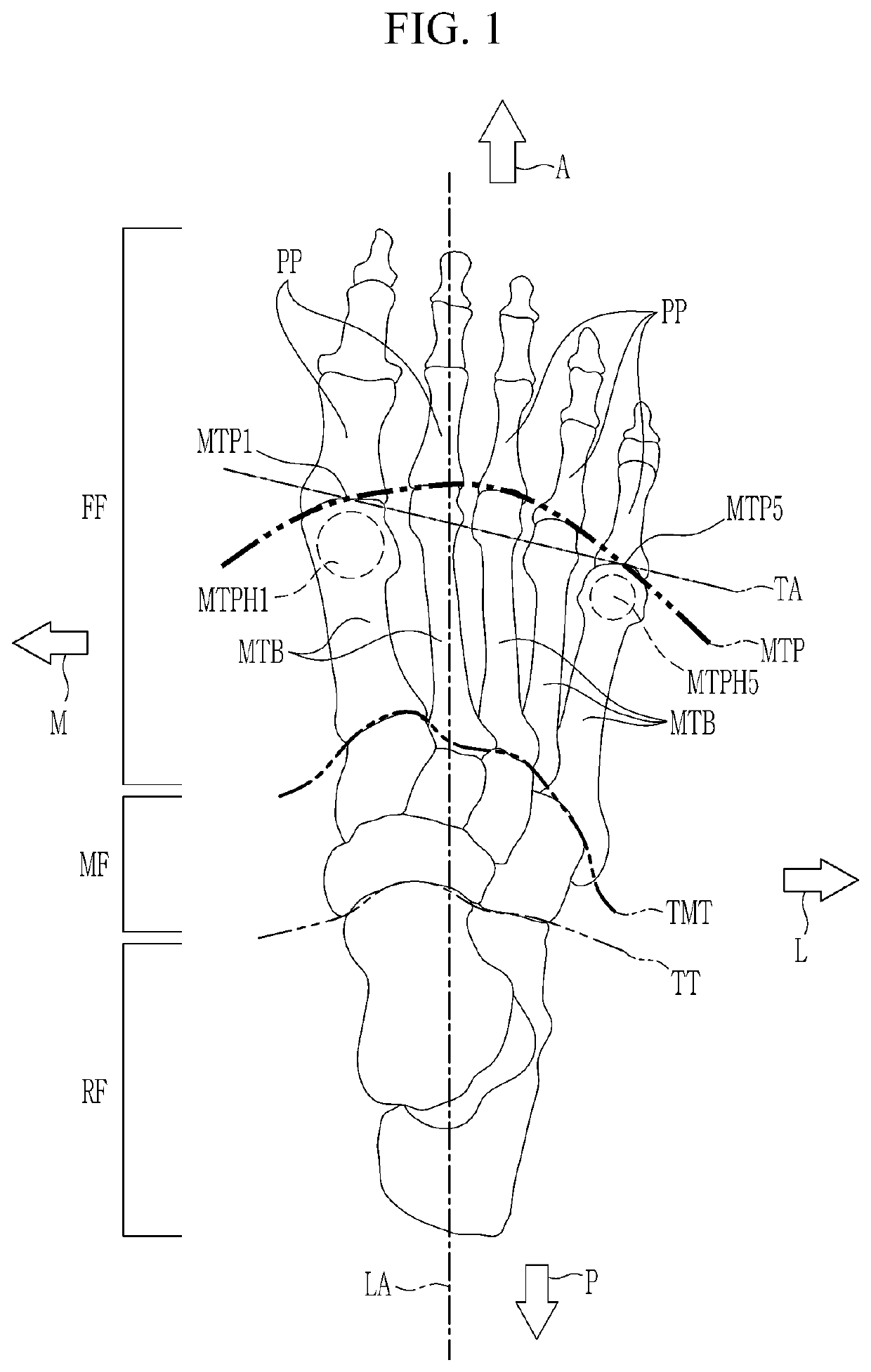
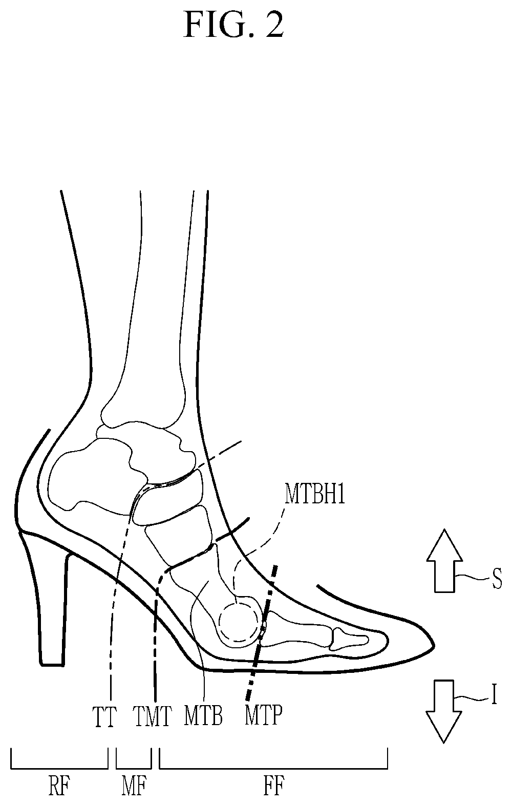
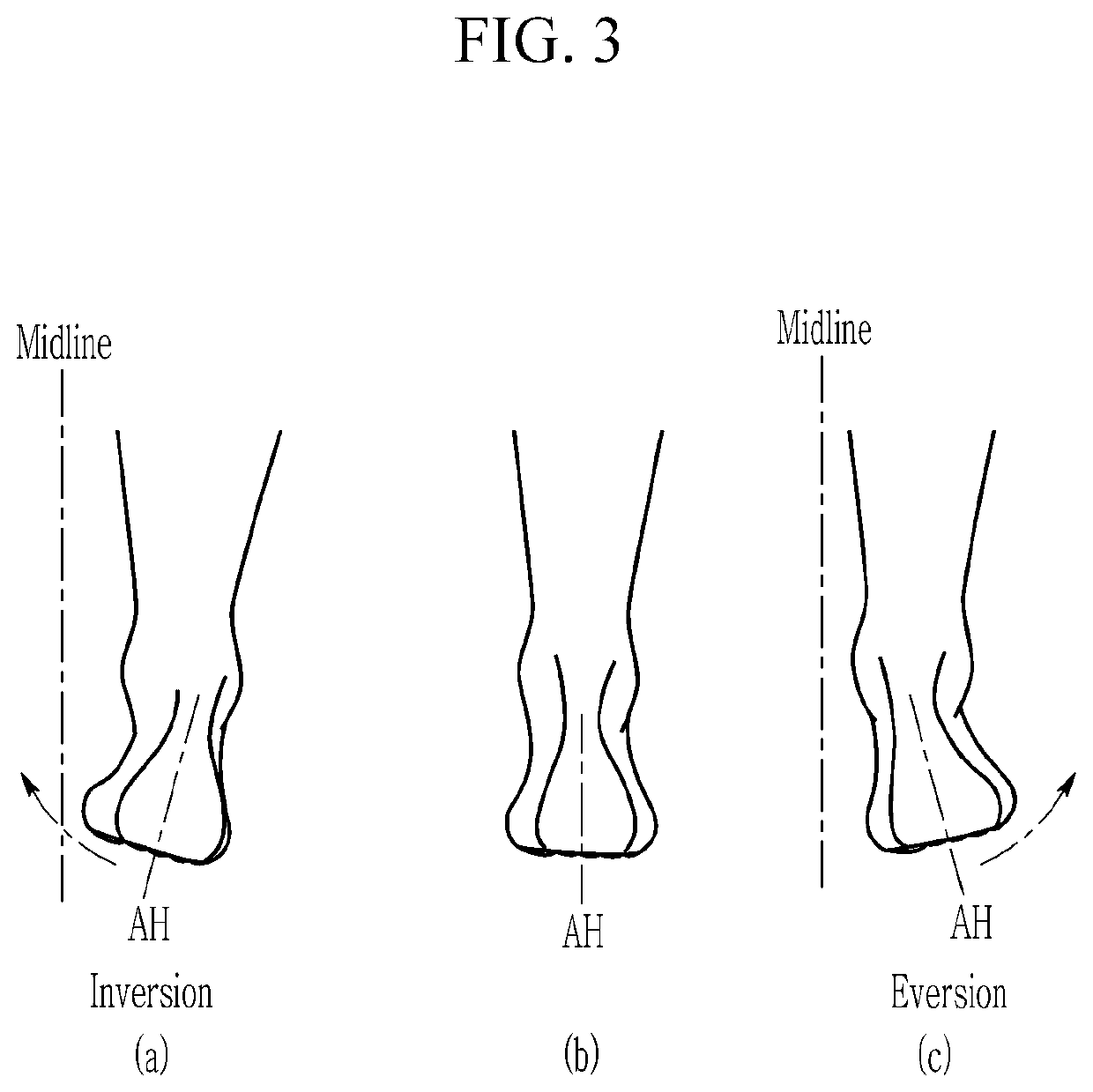
TECHNICAL FIELD[0001]The present invention relates to a high-heeled shoe sole structure and a high-heeled shoe including the same that may have a walking mechanism similar to movement of human walking when a pedestrian wears and walks in high-heeled shoes.BACKGROUND ART[0002]During a human gait cycle, at the heel off and toe off period after the midstance, extension of the metatarsophalangeal joints occurs, and simultaneously, inversion and adduction of the heel of the foot occur.[0003]A pedestrian wearing conventional high-heeled shoes suffers from an ankle sprain due to instability of a rearfoot depending on a high heel, when a body's weight is loaded on the ground while standing or walking. Therefore, a sole structure of the conventional high-heeled shoes is made of a very hard material in which a metal shank is inserted from a rear boundary of a front portion that is a portion where the shoe contacts the ground and is supported on the ground to an end of the rearfoot.[0004]In ad...

Claims


Application Information

Patent Timeline
IPC IPC(8): A43B7/14A43B7/16A43B7/22
CPCA43B7/149A43B7/223A43B7/16A43B7/144A43B7/1485A43B7/142A43B7/143A43B3/12A43B3/128A43B7/1415
Inventor KIM, IL SOO
Owner KIM IL SOO
Why Eureka
Eureka Blog
Learn More