Device for robot-assisted surgery

a robot and surgery technology, applied in the field of robot-assisted surgery, can solve the problems of contaminated surgical instruments and/or endoscopes, contamination of body fluids and/or tissue of patients, contamination of material, etc., and achieve the effect of flexible use of the device and precise and reliable control of the end effector

Pending Publication Date: 2021-12-23
AVATERAMEDICAL GMBH
View PDF0 Cites 1 Cited by
  • Summary
  • Abstract
  • Description
  • Claims
  • Application Information

AI Technical Summary

Benefits of technology

[0029]It is particularly advantageous if a plurality of sensor units are provided, that the number of sensor units corresponds at least to the number of second drive elements, and that at least one sensor unit each detects the angle of rotation of a second drive element. In this way, a particularly precise and reliable control of the end effector is achieved.
[0030]It is advantageous when the instrument unit comprises an instrument with an end effector arranged at a distal end of an instrument shaft, wherein the at least one second drive element is coupled to the end effector and wherein the end effector is movable and / or controllable in at least one degree of freedom with the aid of the at least one second drive element, in particular, in the case of four second drive elements, in four degrees of freedom, wherein in each case two of the second drive elements effect a rotary movement about the longitudinal axis of the instrument shaft and in each case two further second drive elements effect a longitudinal movement in the direction of the longitudinal axis of the instrument shaft. Alternatively, it is advantageous if the instrument unit comprises an endoscope with an endoscope shaft, wherein the at least one second drive element is coupled to the endoscope, the endoscope shaft and / or an optical system of the endoscope such that a movement of the endoscope, the endoscope shaft and / or the optical system is possible in at least one degree of freedom with the aid of the at least one second drive element. This enables a particularly large variety of different instrument units and a particularly flexible use of the device.

Problems solved by technology

With the aid of the telemanipulator system, surgical instruments and / or endoscopes are controlled in their position and orientation on the basis of operator inputs and inevitably come into physical contact with the patient to be operated so that the surgical instruments and / or endoscopes become contaminated with body fluids and / or tissue of the patient to be operated.
Category 1: The material is sterile and becomes contaminated during the surgical procedure.

Method used


Image

  • Device for robot-assisted surgery
  • Device for robot-assisted surgery
  • Device for robot-assisted surgery

Examples


second embodiment

[0065]FIG. 6 shows an instrument unit 500 with a first instrument drive element 502 and a second instrument drive element 504. In this case, an end effector may be movable and / or controllable in two degrees of freedom. The end effector of the instrument unit 500 is a pair of scissors 506 that can be opened and closed, for example. In FIG. 6, the pair of scissors 506 is shown in an open state.

[0066]Alternatively, the end effector may be, for example, an optical system of an endoscope, which is both rotatable about the axis of rotation 52 and movable with the aid of a joint about an axis orthogonal to the axis of rotation 52.

third embodiment

[0067]FIG. 7 shows an instrument unit 600 with altogether four instrument drive elements 602, 604, 606, 608. In this case, an end effector may be movable and / or controllable in four degrees of freedom. For example, the end effector may be a pair of scissors or a pair of forceps. The end effector of the instrument unit 600 is a pair of forceps 610. In this case, for example, both the levers or legs of the pair of forceps 610 are movable relative to each other and the pair of forceps 610 is rotatable and / or tiltable about an X-axis, Y-axis and / or Z-axis. This allows easy and precise positioning of the end effector relative to the operation field. In FIG. 7, the pair of forceps 610 is shown in an open state, as well as tilted out of the axis 52.

[0068]The axis of rotation 52 runs through the circle centers of the four instrument drive elements 602, 604, 606, 608 of the instrument unit 600. The instrument drive elements 602, 604, 606, 608 are arranged in parallel planes of rotation that...

fourth embodiment

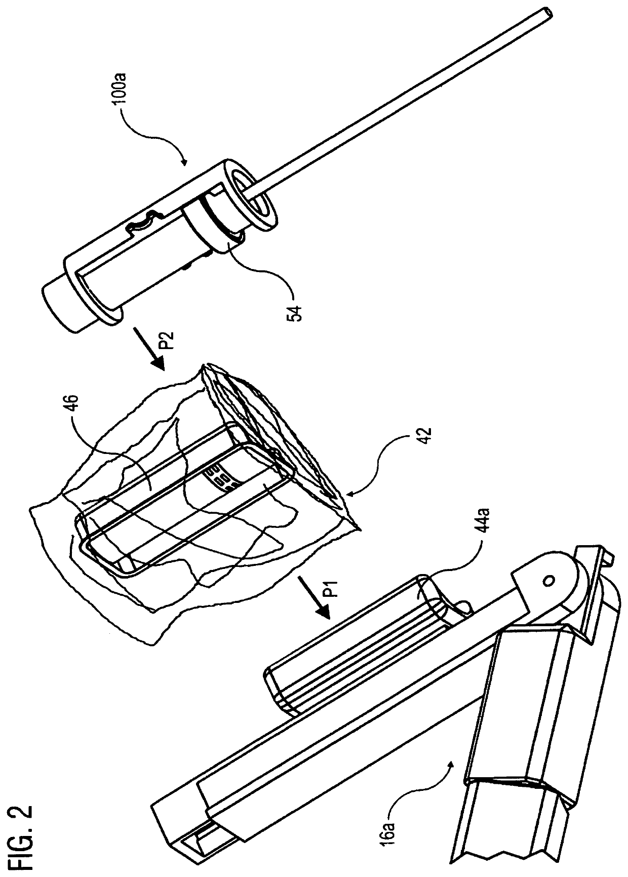
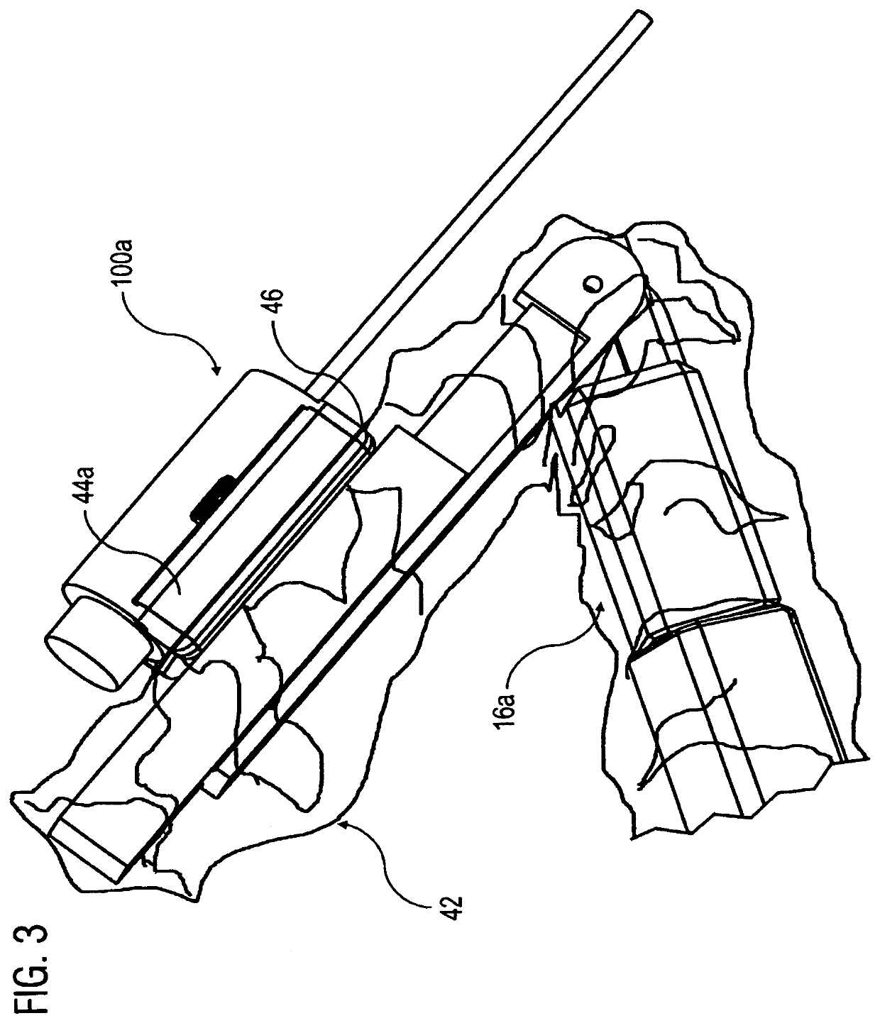
[0073]FIGS. 8 to 10 respectively show an instrument unit 200 and a coupling unit 204 with an electromagnetic drive. FIG. 8 shows a coupling unit drive element 202 in the coupling unit 204. A part 206 of the sterile barrier 42 is put over the coupling unit 204 in the direction of the arrow P3. Subsequently, the instrument unit 200 is coupled to the coupling unit 204 in the direction of the arrow P4.

[0074]The instrument unit 200 comprises an instrument drive element 208. In the coupled state, the coupling unit drive element 202 and the instrument drive element 208 are arranged side by side in the plane of rotation 55 orthogonally to the axis of rotation 52. The dimensionally stable part 206 of the sterile barrier 42 is configured and arranged such that in a region 210 along the plane of rotation 55 of the drive elements 202, 208, the dimensionally stable part 206 of the sterile barrier 42 bears tightly against the coupling unit drive element 202 and does not come into contact with th...


PUM


Abstract

A device for robot-assisted surgery comprises at least one manipulator arm with a non-sterile coupling unit comprising at least one first drive element. Further, the device comprises a sterile instrument unit arranged in a sterile area and comprising at least one second drive element arranged rotatably around an axis of rotation. The first drive element and the second drive element are configured and arranged in a coupled state such that by the first drive element a force can be exerted on the second drive element, for rotation of the second drive element about the axis of rotation, and in the coupled state the first drive element and the second drive element are arranged side by side in a plane of rotation orthogonally to the axis of rotation. Further, the device comprises a sterile barrier which is arranged at least between the first drive element and the second drive element.

Description

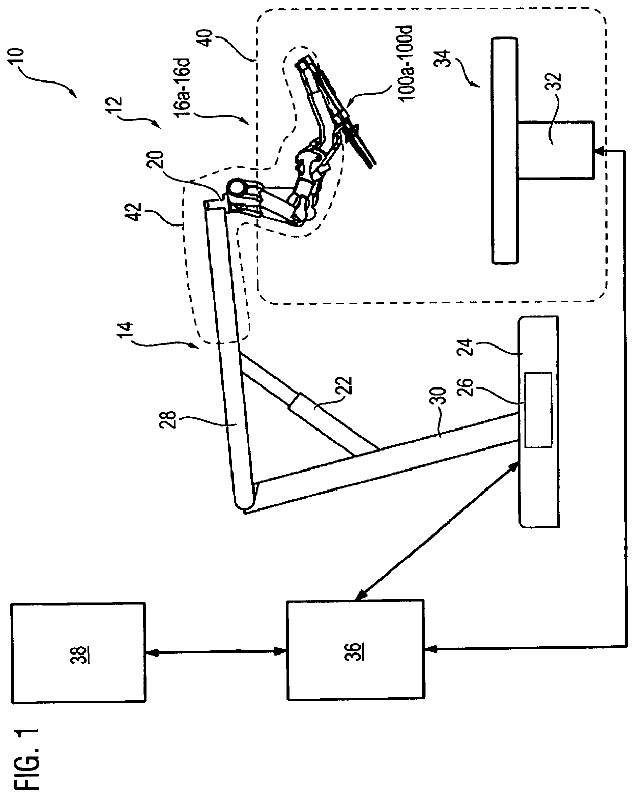
CROSS-REFERENCE TO RELATED APPLICATIONS[0001]This application claims the benefit of German Application 10 2020 116 256.1, filed on Jun. 19, 2020, both of which are incorporated herein in their entireties.TECHNICAL FIELD[0002]The invention relates to a device for robot-assisted surgery comprising at least one manipulator arm with a non-sterile coupling unit having at least one first drive element. The device further has at least one sterile instrument unit arranged in a sterile area and comprising at least one second drive element arranged to be rotatable about an axis of rotation. The instrument unit is couplable to the coupling unit.BRIEF DESCRIPTION[0003]In minimally invasive surgery, so-called telemanipulator systems, also referred to as robot assistance systems, are increasingly used for robot-assisted surgery. The sterile surgical field is protected from the non-sterile elements of the telemanipulator system with the aid of a sterile cover. The sterile cover prevents contaminat...

Claims


Application Information

Patent Timeline
Patent Type & Authority Applications(United States)
IPC IPC(8): A61B50/00A61B34/30A61B34/00B25J19/00B25J13/08
CPCA61B50/00A61B34/30A61B2034/301B25J19/0045B25J13/088A61B34/73A61B34/37A61B2034/302A61B2017/00477A61B46/10A61B2034/305A61B90/98A61B90/361A61B17/29A61B2090/067A61B2017/00876A61B1/0016A61B1/00042
Inventor KEIM, TOBIASJAHN, MICHAELBAUDISCH, TOBIAS DJANGO
Owner AVATERAMEDICAL GMBH
Why Eureka
Try Eureka