Positioning apparatus of a patient's limb

a technology for positioning apparatus and patient's limb, which is applied in the field of orthopaedic surgery, can solve the problems of increasing the amount of traction on the limb, increasing the cost of the operation, and unease for the surgeon, and achieves the effect of reducing the differen

Pending Publication Date: 2021-08-19
MEDACTA INT SA
View PDF0 Cites 0 Cited by
  • Summary
  • Abstract
  • Description
  • Claims
  • Application Information

AI Technical Summary

Benefits of technology

[0044]Preferably, in the position control command mode the electronic control unit is configured to reduce the difference between the detected position and the pre-set position.
[0045]More particularly, in the position control command mode the electronic control unit is preferably configured to command activation of the drive unit so as to move the coupling bracket in the direction of movement, in a way suitable to reduce the difference between the detected position and the pre-set position.

Problems solved by technology

First, it is noted that many known devices must be operated by a dedicated operator. In addition to the surgeon and the surgical technician, the presence of an additional person in the operating room is necessary, with a consequent increase in the costs of the operation. In addition, the need to delegate the lower limb positioning procedures to a third-party operator may cause unease for the surgeon, forced to coordinate their operation with the interventions of another person.
However, in the current state of the art, moving the limb in extension while simultaneously holding it in traction may uncontrollably increase the amount of traction on the limb, causing overdistensions of or lacerations to the muscles or ligaments.
The Applicant has however observed that a complete release of traction during extension movements is not always desirable.
On the contrary, it has been observed that total release of traction during the extension movement may, for example, cause sudden movements of the traction slider which may make the leg jerk and consequently cause the retractors in the wound to lose their stability.
These sudden and uncontrolled movements can cause small muscle lesions and require the surgeon to reposition the retractors.
In addition, known devices still require the intervention of a dedicated operator to apply the appropriate rotational movements to the patient's limb while the surgeon operates on the head of the femur or other parts of the leg.
Management of such small adjustments by servo-controlled actuators may not be intuitive, and the required accuracy is difficult to achieve.

Method used


Image

  • Positioning apparatus of a patient's limb
  • Positioning apparatus of a patient's limb
  • Positioning apparatus of a patient's limb

Examples


Embodiment Construction

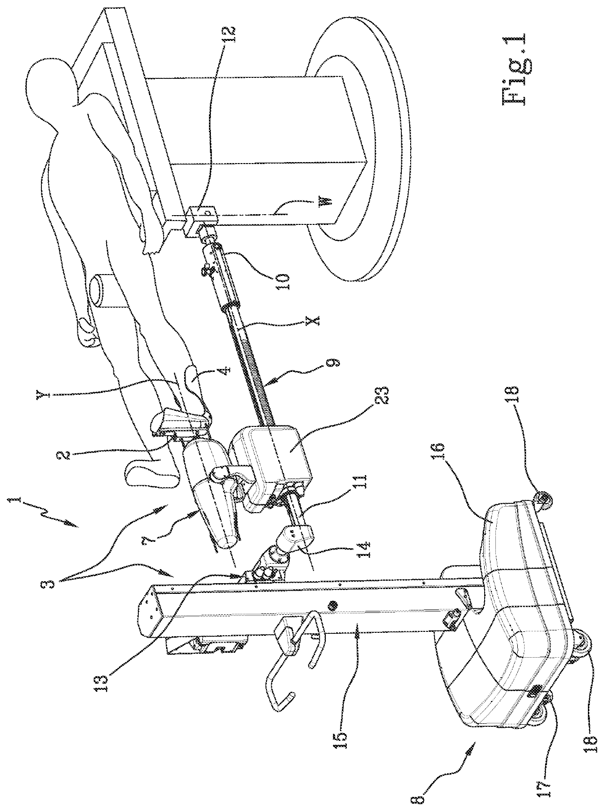
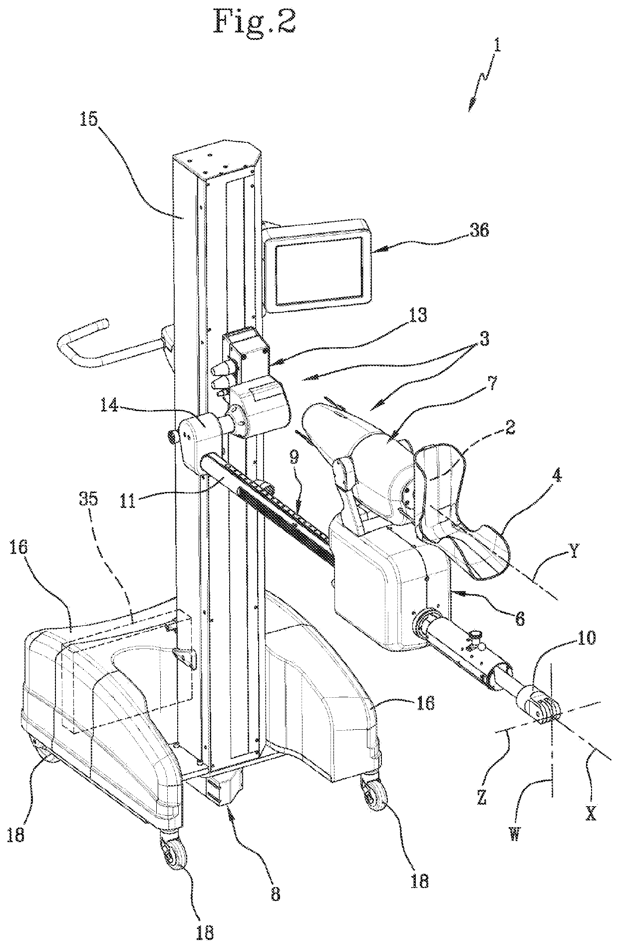
[0078]In the above figures, the number 1 designates in its entirety a patient limb positioning apparatus, according to the present invention.

[0079]In the example shown, the apparatus 1 is suitable for use during performance of surgical procedures with anterior approach for the partial or total replacement of the hip prosthesis of a patient, in order to position, move and / or adequately stress the patient's leg during surgery.

[0080]The apparatus 1 essentially comprises a coupling bracket 2, detachably engageable with the patient's limb, and a movement assembly 3, operating on the coupling bracket 2 to move it according to a plurality of axes of movement X, Y, Z, W.

[0081]The coupling bracket 2 can be combined with a shoe 4 suitable to fit on the foot of the patient, lying in the supine position on an operating table 5.

[0082]In the example shown, axes of movement are identified including the axes X, Y, Z, W:

[0083]a traction axis X, typically horizontal, substantially parallel to the pat...


PUM


Abstract

A patient limb positioning apparatus comprises a movement assembly operating on a coupling bracket which can be engaged with the patient's limb, to move the limb according to a plurality of axes of movement. The movement assembly comprises, for at least one of said axes of movement, a drive unit which can be activated to move the coupling bracket according to a predetermined direction of movement. A load transducer detects a load transmitted between the coupling bracket and the drive unit in the respective direction of movement, to emit a signal representative of a detected load value. An electronic control unit is selectively switchable to a load control command mode and is suitable to cyclically compare the measured load value with a pre-set load value, to control activation of the drive unit when the detected load value differs from the pre-set load value.

Description

TECHNICAL FIELD[0001]The present invention applies to the field of orthopaedic surgery and refers in particular to an apparatus for positioning a patient's limb, in particular a lower limb, during an operation. The apparatus is especially useful in hip replacement operations with anterior approach.KNOWN ART[0002]The known art proposes different surgical techniques for the partial or total replacement of a patient's hip prosthesis.[0003]A recently introduced technique, particularly appreciated because of its low invasiveness, involves an anterior approach which reaches the hip joint by passing through the intermuscular plane between the tensor of the fascia lata and the sartorius / rectus femoris. This technique is usually identified by the acronym AMIS®.[0004]To perform this technique correctly, it is however necessary to perform a series of manipulations of the lower limb of the patient so that the surgeon is always able to operate in conditions of optimal access to the surgical site...

Claims


Application Information

Patent Timeline
Patent Type & Authority Applications(United States)
IPC IPC(8): A61G13/12A61G13/00
CPCA61G13/1245A61G13/0081A61G2203/10A61G2203/42A61G2203/32A61G2203/20
Inventor SICCARDI, FRANCESCOBERNARDONI, MASSIMILIANOROSSI, ERMETELAUDE, FREDERICRIGHETTINI, PAOLO
Owner MEDACTA INT SA
Why Eureka
Try Eureka