
Method for operating a switching hump system and control means for the same

a technology of switching hump and control means, which is applied in the direction of classification yard switching systems, train hauling devices, transportation and packaging, etc., can solve the problems of unsatisfactory impact speed, inability to guarantee the required shunting quality, and insufficient braking capacity of classification track retarders, so as to improve the performance of the hump yard and the operation method is more automated.

Inactive Publication Date: 2015-09-29
SIEMENS AG
View PDF18 Cites 0 Cited by
  • Summary
  • Abstract
  • Description
  • Claims
  • Application Information

AI Technical Summary

Benefits of technology

The present invention provides a method for operating a switching hump yard that allows for even greater automation of the hump yard's operation and improved performance. The method allows for automatic operation of the hump yard when the occupancy of a classification track extends into the retarder or beyond. The method also allows for the formation of trains whose length exceeds the useful length of the classification track, ensuring efficient operation of the hump yard. The control device for the hump yard supports the method and provides precise and reliable control of the lower main retarder by taking into account specific cut data such as weight or rolling resistance of the cut.

Problems solved by technology

This means that it is already recognized before the cut actually reaches the lower main retarder that the cut will not pass through the classification track retarder as planned, or at least not fully.
In relation to the cut concerned, the braking capacity of the classification track retarder is therefore not available, or at least not fully available, for the purpose of braking the cut.
In the event of a corresponding occupancy level of a classification track, conventional methods for the operation of hump yards can no longer guarantee the required shunting quality, i.e. in particular the prevention of an unacceptably high impact speed of the cuts relative to standing cars.
However, both cases result in considerable delays and impediments to the humping operation.
With regard to possible manual braking of the cars, it must also be taken into account that such an approach will often fail simply because the cars to be braked do not have a handbrake, particularly in the case of newer freight cars.

Method used


Image

  • Method for operating a switching hump system and control means for the same
  • Method for operating a switching hump system and control means for the same

Examples


Embodiment Construction

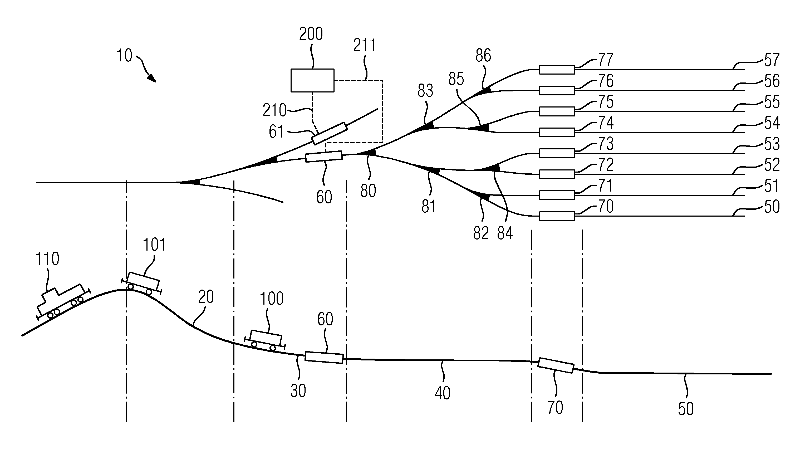
[0027]A hump yard 10 can be seen in the FIGURE. In this case, the upper part of the FIGURE shows the track diagram of the hump yard 10 and the lower part of the FIGURE shows the profile or a longitudinal section of the hump yard 10.

[0028]According to the illustration in the FIGURE, the hump yard 10 as part of a switching system for rail traffic has a hump ramp 20 which is connected to an intermediate slope 30, a sorting zone 40 comprising switching points 80 to 86, and classification tracks 50 to 57. Retarders in the form of lower main retarders 60, 61 and classification track retarders 70 to 77 are also shown in the FIGURE.

[0029]In addition to the cited components of the hump yard 10, the FIGURE also includes an exemplary illustration of cuts 100 and 101, which have been pushed or humped over the hump by a humping locomotive 110 and then move along the hump yard 10 under the influence of gravity.

[0030]In the context of the further description, it is assumed that the classification ...


PUM


Abstract

A method for operating a switching hump yard, wherein in a first operating mode a lower master retarder is controlled in such a manner that cuts in the form of descending cars or groups of cars reach a classification track retarder of a classification track at a speed that is lower than a first threshold, a switch is made from the first operating mode into a second operating mode if a target for a cut is found in or in front of the classification track retarder of the classification track, and in the second operating mode the master retarder is controlled in such a manner that the cut reaches the determined target in or in front of the classification track retarder at a speed that is lower than a second threshold. We also describe a controller for controlling such a switching hump yard.

Description

BACKGROUND OF THE INVENTIONField of the Invention[0001]In switching hump yards, cars or car groups (also referred to as cuts) are sorted from a hump track into different classification tracks using the force of gravity that acts on the cuts. For reasons of efficiency and reliability, the operation of the hump yard is usually automated to a large extent in this type of configuration. A suitable automatic control system for this purpose is disclosed, for example, in the company publication “Automatisierungssystem für Zugbildungsanlagen MSR32—Mehr Effizienz and Sicherheit in the Güterverkehr”, Order No. A19100-V100-B898-V1, Siemens AG, 2010. In this case, automatic speed adjustment of the cuts is achieved by controlling a lower main retarder accordingly, such that the entry speed of the cuts into the next braking stage, in the form of a classification track retarder, does not exceed a first threshold value. This ensures that adequate braking of the cuts can be achieved by the classific...

Claims


Application Information

Patent Timeline
Patent Type & Authority Patents(United States)
IPC IPC(8): B61K7/12B61K7/02B61J3/02B61L17/00B61L25/02
CPCB61K7/02B61J3/02B61K7/12B61L17/00B61L25/021
Inventor DIERKES, GERHARDHUSTER, MARIOJUNG, MARTIN
Owner SIEMENS AG
Learn More