Synchronous converter having under- and overcurrent protection

a technology of synchronous converters and protection devices, applied in the field of synchronous converters, can solve the problems of reducing circuit complexity, reducing circuit board space, and fewer components

Active Publication Date: 2021-12-23
TRIDONIC
View PDF0 Cites 0 Cited by
  • Summary
  • Abstract
  • Description
  • Claims
  • Application Information

AI Technical Summary

Benefits of technology

[0044]This advantageously makes it possible to protect against overcurrents in any conductor direction.

Problems solved by technology

This reduces circuit complexity, calls for fewer components and saves circuit board space.

Method used


Image

  • Synchronous converter having under- and overcurrent protection
  • Synchronous converter having under- and overcurrent protection
  • Synchronous converter having under- and overcurrent protection

Examples


Embodiment Construction

[0051]The invention will be explained in more detail below using preferred embodiments and with reference to the drawings. A description of exemplary embodiments in specific fields of application does not signify a limitation of these fields of application. Elements of schematic representations are not necessarily reproduced to scale, but rather in such a way that their function and purpose will be understood by a person skilled in the art. Unless expressly indicated otherwise, the features of the various embodiments can be combined with one another.

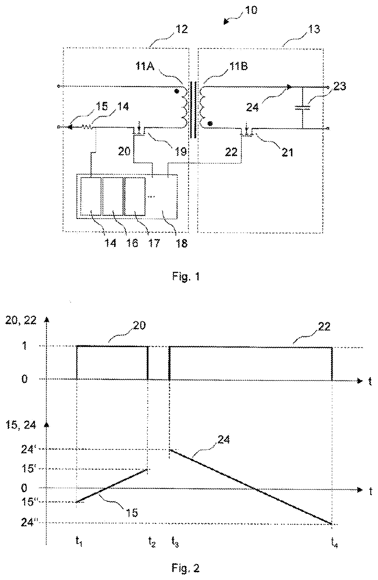
[0052]FIG. 1 schematically shows a synchronous converter 10 according to one exemplary embodiment, while FIG. 2 schematically illustrates a time curve of selected electrical quantities 20, 22, 15, 24 of the synchronous converter10 according to the exemplary embodiment.

[0053]The synchronous converter 10 is configured as a synchronous flyback converter, which comprises a transformer 11A, 11B with a predetermined winding ratio, which couple...


PUM


Abstract

The invention relates to a synchronous converter (10) comprising a transformer (11A, 11B) having a predefined winding ratio, which couples a supply-side (12) and a load side (13) of the synchronous converter (10), which are each allocated limit current intensities (15′, 15″, 24′, 24″); detection means (14), which are configured to detect a current intensity (15) on one side (12) from the supply side (12) and the load side (13); conversion means (16), which are configured to provide the limit current intensities (24′, 24″) from the other side (13) from the supply-side (12) and the load side (13), converted via the predefined winding ratio, as corresponding limit current intensities (15*, 15**) on the one side (12); and comparison means (17), which are configured to compare the detected current intensity (15) with the limit current intensities (15′, 15″) of the one side (12) and with the corresponding limit current intensities (15*, 15**) on the one side (12).

Description

CROSS REFERENCE TO RELATED APPLICATIONS[0001]The present application is the U.S. national stage application of international application PCT / EP2019 / 050762 filed Jan. 14, 2019, which international application was published on Aug. 15, 2019 as International Publication WO 2019 / 154590 A1. The international application claims priority to German Patent Application 10 2018 201 878.2 filed Feb. 7, 2018.FIELD OF THE INVENTION[0002]The present invention relates to synchronous converters and methods for the current protection of synchronous converters, as well as to related operating devices and lighting systems. More particularly, the present invention relates to synchronous converters generally having different limit current intensities on a supply side and a load side.BACKGROUND OF THE INVENTION[0003]Operating devices for operating LED modules use known converter architectures in order to provide a load voltage adapted for the LED modules to be operated from a predetermined input voltage, ...

Claims


Application Information

Patent Timeline
Patent Type & Authority Applications(United States)
IPC IPC(8): H02M3/335H02M1/32H02M1/00H05B45/385
CPCH02M3/33592H05B45/385H02M1/0009H02M1/32H02M3/33523H02M1/325
Inventor DE CLERCQ, LUDWIG ERASMUS
Owner TRIDONIC
Why Eureka
Try Eureka