
Analog decoding method and decoder

an analog decoding and analog circuit technology, applied in the field of analog decoding methods and decoding, can solve the problems of linear increase in the complexity of the analog circuit, limited application of relatively short and simple codes, and inability to achieve the effects of reducing circuit complexity

Active Publication Date: 2006-07-04
PIECE FUTURE PTE LTD
View PDF5 Cites 13 Cited by
  • Summary
  • Abstract
  • Description
  • Claims
  • Application Information

AI Technical Summary

Benefits of technology

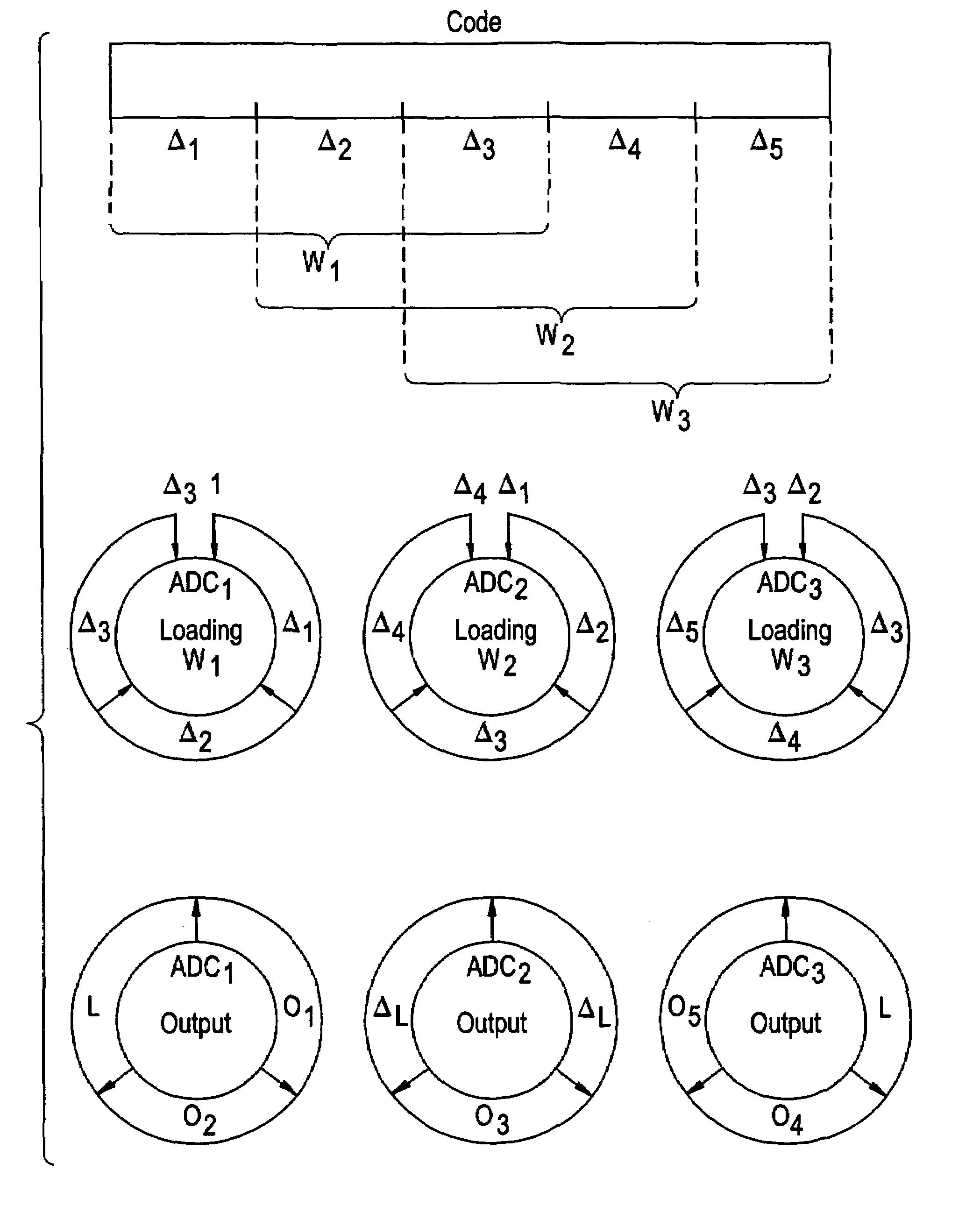
[0009]The present invention provides an analog decoder that implements a fraction of the overall block length of the code trellis and thus significantly reduces circuit complexity. Furthermore, a single decoder core may be used for various block lengths.

Problems solved by technology

As a general trend, encoding techniques become more complex to facilitate a variety of desirable applications, such as high speed downlink packet access (for example).
However, the complexity of the analog circuit grows linearly with the block length of the code since the whole code trellis is mapped onto the analog circuit.
Thus, the analog decoder has been limited to applications involving relatively short and simple codes.
Another problem is that a particular analog decoder can only be used for a fixed coding scheme (i.e., block length, rate, memory, and interleaver).

Method used


Image

  • Analog decoding method and decoder
  • Analog decoding method and decoder
  • Analog decoding method and decoder

Examples


Embodiment Construction

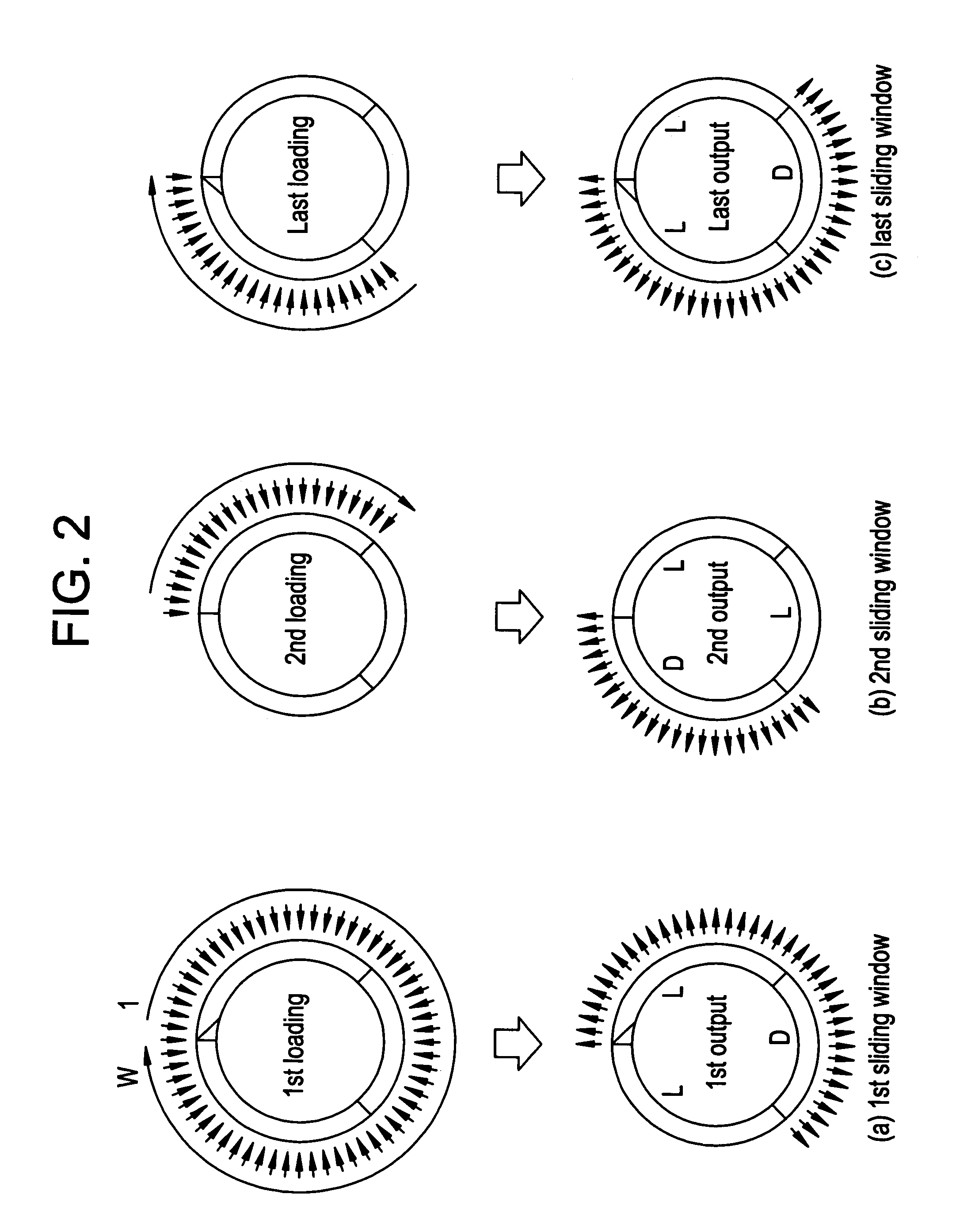
[0022]To facilitate understanding of the present invention, the following description is presented in three sections. Section I discusses two conventional decoding techniques inclusive of (A) a posteriori probability (“APP”) decoding and (B) sliding window decoding. Section II presents a generalized sliding window decoding technique as applied to (A) terminated convolutional codes and (B) tailbiting convolution codes, and in subpart (C) introduces a tailbiting trellis structure. Section III presents two exemplary, non-limiting embodiments of the invention inclusive of (A) a single core—iterative decoding embodiment and (B) a multiple core—parallel decoding embodiment.

[0023]Unless otherwise stated, sections I, II, and III are discussed in view of the following considerations: a rate 1 / 2 convolutional encoder with memory m and constraint length m+1, where N info bits are encoded into a code word of length 2N; and the trellis of the code is terminated using 2 m additional bits. Typical...


PUM


Abstract

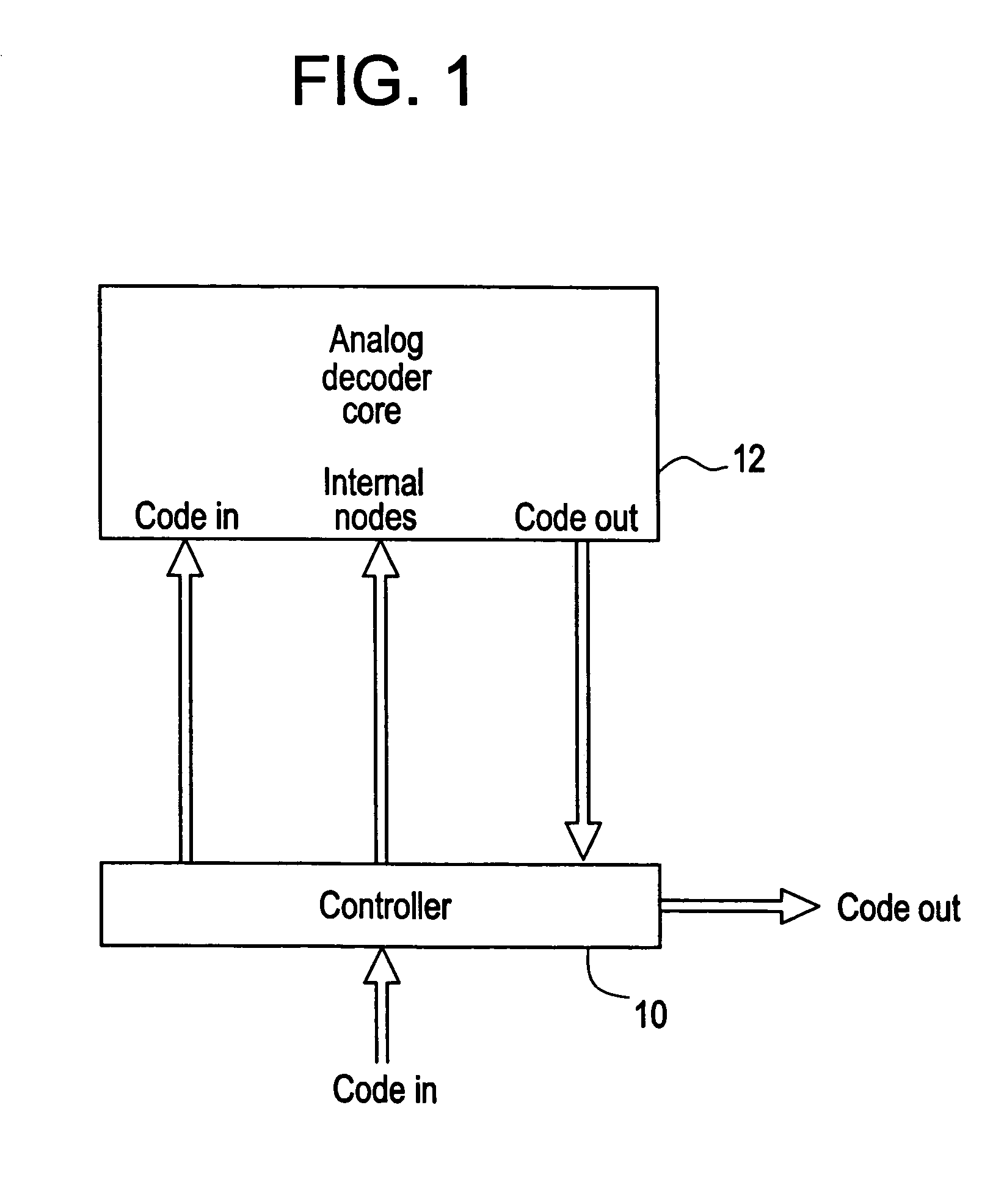
An analog decoder includes a controller and an analog decoder core. The analog decoder core has an input of an input length that is less than a code length of the code data. If only a single analog decoder core is implemented, then the controller applies a portion of the code data to the analog decoder core prior to each of a plurality of read operations in which decoded data is read from the analog decoder core. Alternatively, if a plurality of analog decoder cores is implemented, then the controller may apply a portion of code data onto each of the analog decoder cores prior to a single read operation associated with each of the analog decoder cores.

Description

BACKGROUND OF THE INVENTION[0001]1. Field of the Invention[0002]The present invention relates in general to an analog decoding method and decoder.[0003]2. Description of Related Art[0004]Channel coding is used in many communication systems. As a general trend, encoding techniques become more complex to facilitate a variety of desirable applications, such as high speed downlink packet access (for example). It is therefore necessary to provide appropriate decoding hardware.[0005]A channel decoder is commonly implemented in the digital domain. There are two types of digital decoders. The first digital decoder implements an optimal decoding technique (or “APP” decoding) in which symbol error probability is minimized. The APP decoder for a trellis code performs a forward (or “alpha”) recursion starting at the beginning of the code block (code trellis) and a backward (or “beta”) recursion starting at the end of the code block (code trellis). The decoder output is calculated based on the r...

Claims


Application Information

Patent Timeline
Patent Type & Authority Patents(United States)
IPC IPC(8): H03M7/00H03M1/00H03M13/39
CPCH03M13/3916
Inventor MOERZ, MATTHIAS
Owner PIECE FUTURE PTE LTD
Learn More