Circuit and method for aligning data transmitting timing of a plurality of lanes

a data transmission and plurality of lanes technology, applied in the direction of digital transmission, generating/distributing signals, instruments, etc., can solve the problems of affecting the performance of other peripheral devices, which are connected to the same pci bus, and the inability of the pci bus to meet the requirements of users, so as to reduce the complexity of the circuit and improve the performance of aligning the data transmission timing

Active Publication Date: 2007-05-31
VIA TECH INC
View PDF8 Cites 17 Cited by
  • Summary
  • Abstract
  • Description
  • Claims
  • Application Information

AI Technical Summary

Benefits of technology

[0012] It is an advantage of the present invention that an offset value is calculated dynamically. Therefore, when the numbers of compensating clock cycles are calculated, a simple logic operation is implemented to figure out differences between the count values and the offset value. In other words, the circuit and the method of aligning data transmitting timing according to the present invention do not require a complicated comparing algorithm and a time-consuming searching procedure for finding the minimum value among the count values, which reduces the circuit complexity and improves the performance of aligning the data transmitting timing.
[0013] These and other objectives of the present invention will no doubt become obvious to those of ordinary skill in the art after reading the following detailed description of the preferred embodiment that is illustrated in the various figures and drawings.

Problems solved by technology

However, with the development of disk array and gigabit Ethernet, the PCI bus is unable to meet requirements requested by the users.
Therefore, other peripheral devices, which are connected to the same PCI bus, are greatly affected owing to the image data occupying most of the limited bandwidth.

Method used


Image

  • Circuit and method for aligning data transmitting timing of a plurality of lanes
  • Circuit and method for aligning data transmitting timing of a plurality of lanes
  • Circuit and method for aligning data transmitting timing of a plurality of lanes

Examples


first embodiment

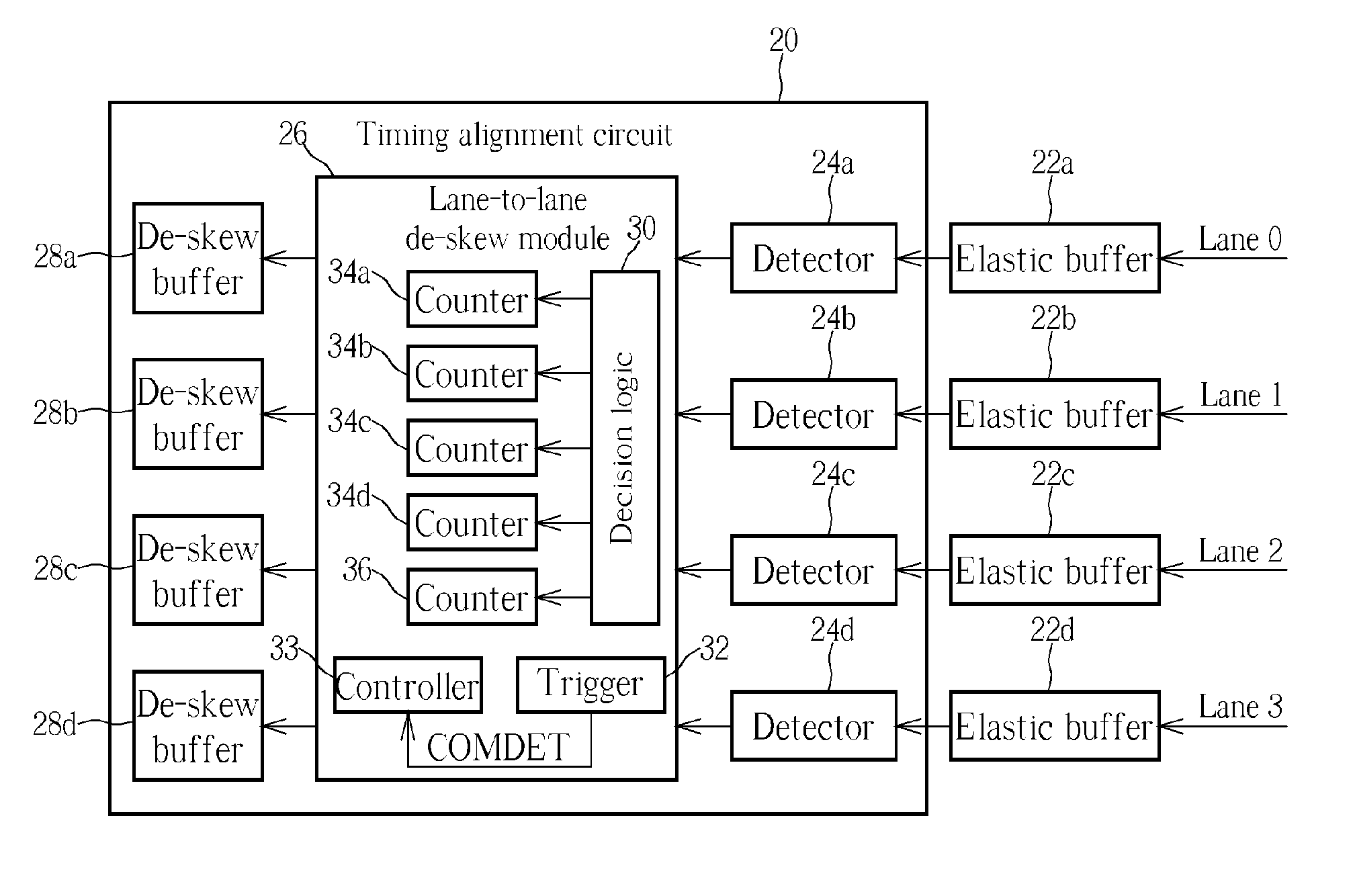
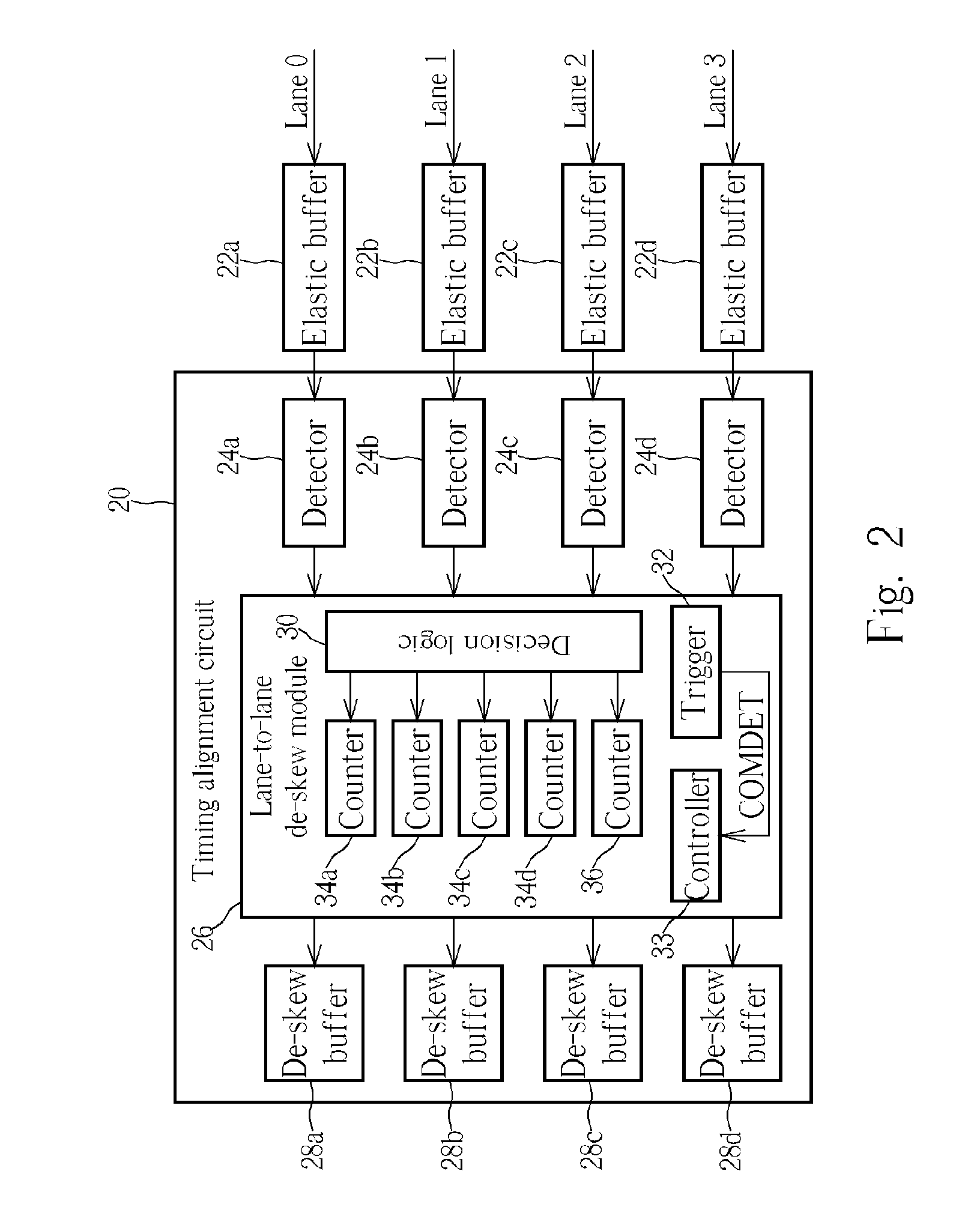
[0019] The controller 33 reads the count values and the offset value counted by the counters 34a, 34b, 34c, 34d, 36 for determining the compensative clock cycle required to compensate for the data transmitting timing of the lanes Lane0, Lane1, Lane2, and Lane3. The related operation is detailed as follows. Please refer to FIG. 2 in conjunction with FIG. 3. FIG. 3 is a diagram illustrating a procedure of aligning the data transmitting timing of the lanes Lane0, Lane1, Lane2, and Lane3 through the timing alignment circuit 20 according to the present invention. When a detector 24a, 24b, 24c, 24d detects a COM symbol within the ordered sets, the decision logic 30 sets count values of the counters 34a, 34b, 34c, 34d according to the following rules.

[0020] Rule (1): If an SKP symbol is deleted on a lane, a count value corresponding to the lane is set to an initial value equaling 3.

[0021] Rule (2): If an SKP symbol is added on a lane, a count value corresponding to the lane is set to an i...

second embodiment

[0039] Regarding the above operations, the timing alignment circuit 20 handles the data transmitting timing of the lanes Lane0, Lane1, Lane2, Lane3 through an 8-bit computing architecture. That is, the timing alignment circuit 20 processes one byte delivered via each lane Lane0, Lane1, Lane2, Lane3 within one clock cycle. Please refer to FIG. 2 in conjunction with FIG. 4. FIG. 4 is a diagram illustrating a procedure of aligning the data transmitting timing of lanes Lane0, Lane1, Lane2, and Lane3 through the timing alignment circuit 20 according to the present invention. In this preferred embodiment, the timing alignment circuit 20 handles the data transmitting timing of the lanes Lane0, Lane1, Lane2, Lane3 through a 16-bit computing architecture, so the timing alignment circuit 20 now processes two bytes delivered via each lane Lane0, Lane1, Lane2, Lane3 within one clock cycle. Similarly, when detectors 24a, 24b, 24c, 24d detect COM symbols within ordered sets, the decision logic 30...


PUM


Abstract

A circuit and a method for aligning data transmitting timing of a plurality of lanes. The method includes utilizing different initial values to reset a count value corresponding to a lane when a plurality of COM symbols are detected on the lane, utilizing an increment value to increase the count value corresponding to the lane when a COM symbol is not detected on the lane, and utilizing a plurality of count values corresponding to the lanes to align data transmitting timing of the lanes when a COM symbol is not detected on the lanes within a predetermined period of time.

Description

CROSS REFERENCE TO RELATED APPLICATIONS [0001] The application is a continuation of applicant's earlier application, Ser. No. 10 / 710,264, filed Jun. 30, 2004, which in turn claims the benefit of provisional application Ser. No. 60 / 483,927, filed Jul. 2, 2003. The entirety of both applications is hereby incorporated by reference.BACKGROUND OF THE INVENTION [0002] 1. Field of the Invention [0003] The present invention relates to a circuit and a method for controlling data transmission. More specifically, the present invention discloses a circuit and a method for aligning data transmitting timing of a plurality of lanes. [0004] 2. Description of the Prior Art [0005] Generally speaking, data transmission in a computer system requires a data bus used for transferring predetermined data from a source device to a target device. For instance, a widely used PCI bus is capable of providing a bandwidth of 133 MB / s. However, with the development of disk array and gigabit Ethernet, the PCI bus i...

Claims


Application Information

Patent Timeline
Patent Type & Authority Applications(United States)
IPC IPC(8): G06F1/04G06F5/06G06F13/36G06F13/38
CPCG06F13/385
Inventor TSENG, WAYNE
Owner VIA TECH INC
Why Eureka
Try Eureka