MIMO-CDMA apparatus and the coding/decoding method thereof

a digital modulation and coding technology, applied in the field of multi-access digital modulation apparatus, can solve the problems of too large dynamic range, too large peak-to-average power ratio (papr) and other problems, to achieve the effect of reducing the papr of output signals, reducing the complexity of rf circuits in communication systems, and improving the signal distortion phenomenon of rf circuits

Inactive Publication Date: 2007-06-14
NAT CHUNG SHAN INST SCI & TECH
View PDF7 Cites 15 Cited by
  • Summary
  • Abstract
  • Description
  • Claims
  • Application Information

AI Technical Summary

Benefits of technology

[0005] The purpose of the present invention is to provide a MIMO-CDMA apparatus. By using the feature of single-carrier transmission in CDMA, the PAPR of output signals can be reduced, signal distortion phenomenon of RF circuits in communication systems can be improved, and RF circuit complexity can be decreased.
[0006] Another purpose of the present invention is to provide a MIMO-CDMA apparatus. By adopting multiple antenna for receiving and by using the feature of low space correlation at receiver side, serious signal distortions due to single-channel fading can be avoided.
[0007] Another purpose of the present invention is to provide a MIMO-CDMA apparatus. By using preamble-spreading codes and space-time block coding technologies, multi-path and frequency-offset problems can be conquered.
[0017] The present invention combines the concepts of MIMO and CDMA to make MIMO apparatuses have the high gain of multi-path transmission and avoid the problems of communication quality due to fading of specific frequencies or channel fading. Meanwhile, by using preamble-spreading codes and STBC technologies, the multi-path effect and the frequency-shift problem can be conquered.

Problems solved by technology

However, because MIMO-OFDM transmits by synthesizing multiple subcarriers, the peak-to-average power ratio (PAPR) and the dynamic ranges thereof goes too large.
In such a circumstance, radio-frequency (RF) power amplifiers, digital-to-analog converters (DACs), and analog-to-digital converters (ADCs) need substantial linear operating ranges to prevent signals from distortion, which makes the RF circuit design more complicated.

Method used


Image

  • MIMO-CDMA apparatus and the coding/decoding method thereof
  • MIMO-CDMA apparatus and the coding/decoding method thereof
  • MIMO-CDMA apparatus and the coding/decoding method thereof

Examples


Embodiment Construction

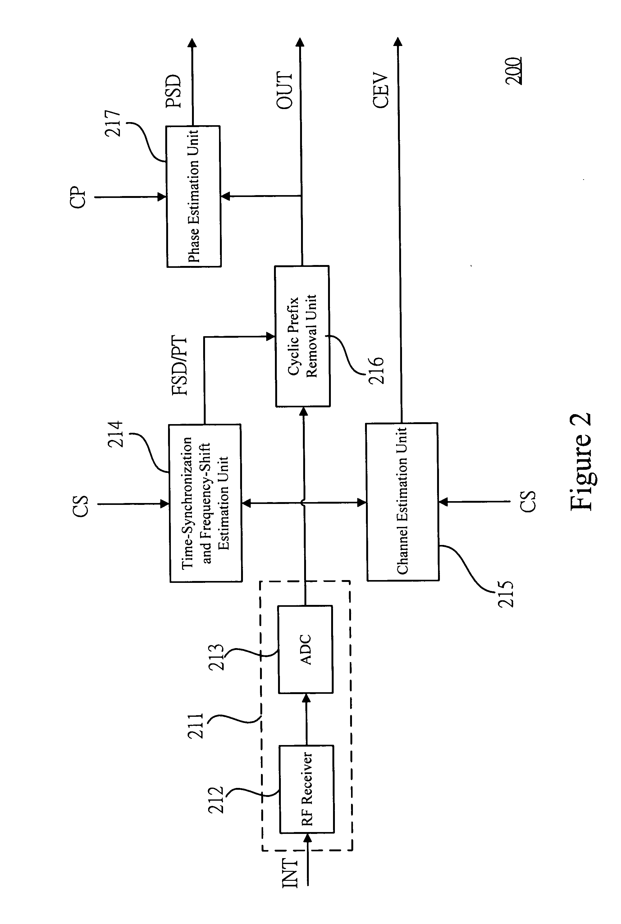
[0024] A MIMO-CDMA apparatus has a transmitter side and a receiver side. The transmitter side is a combination of the MIMO-CDMA apparatus and a plurality of transmitting antennas; the receiver side is a combination of the MIMO-CDMA apparatus and a plurality of receiving antennas. In order to make the person skilled in the art understand the schemes of the present invention more clearly, in the following, a 2-input 2-output CDMA apparatus (abbreviated as 2*2MIMO-CDMA apparatus thereinafter) is used as an example.

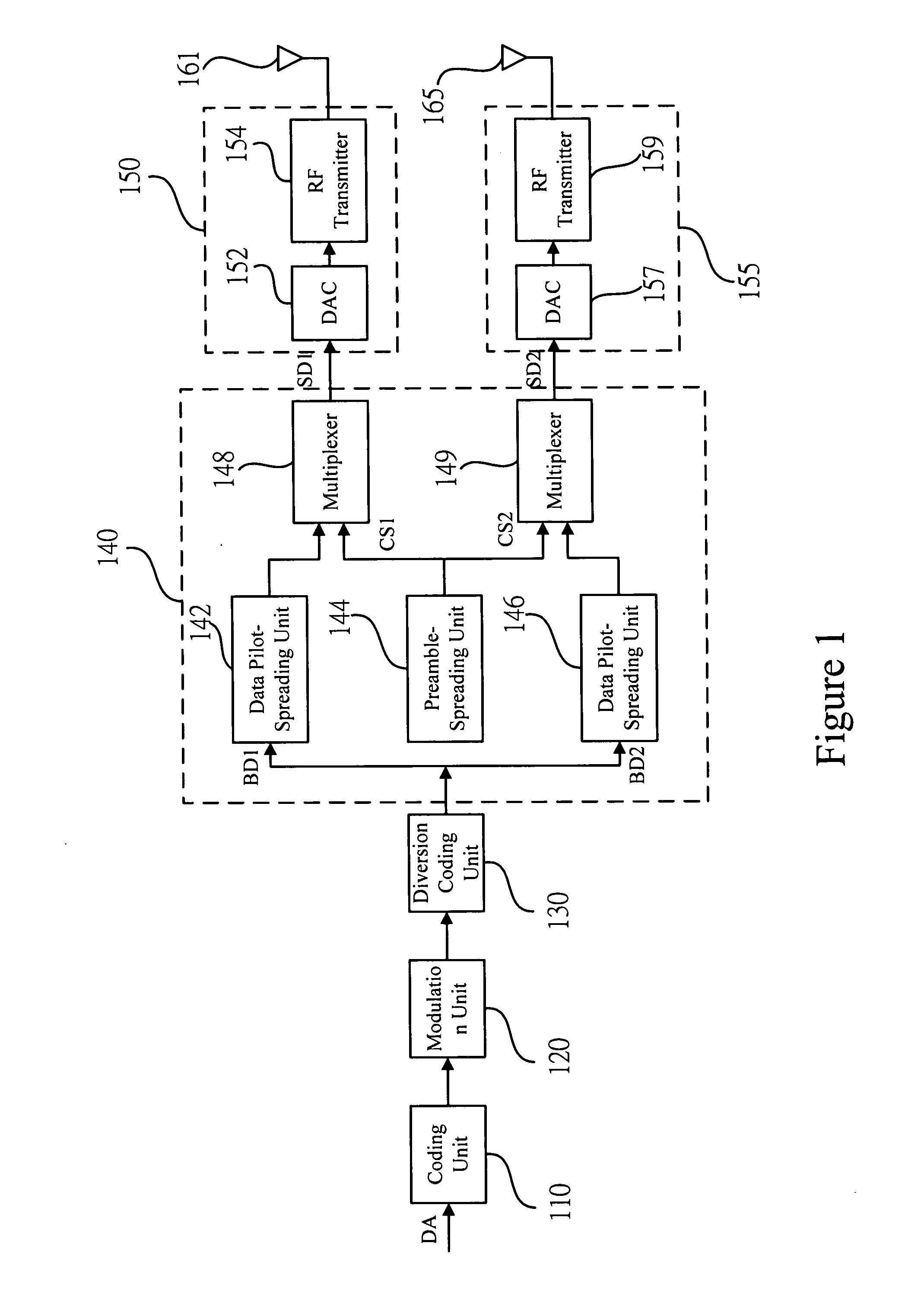
[0025] First, the transmitter side of the 2*2MIMO-CDMA apparatus will be described. FIG. 1 is a block diagram of the transmitter side of a 2*2MIMO-CDMA apparatus according to an embodiment of the present invention. In the present embodiment, the transmitter side of the 2-input 2-output CDMA apparatus will be abbreviated as the transmitter side of the 2*2MIMO-CDMA thereinafter. The transmitter side of the 2*2MIMO-CDMA includes a coding unit 110, a modulation unit 120, a diver...


PUM


Abstract

A Multiple-Output Multiple-Input Code-Division Multiple Access (MIMO-CDMA) apparatus and the coding method thereof. The apparatus includes a transmitter side and receiver side. Both of the transmitter side and the receiver side have a plurality of antennas for achieving the effect of multi-path transmission and receiving. In addition, at the receiver side, use preamble-spreading codes and space-time block coding technology to eliminate multi-path signal interference as well as to modify carrier frequency shift of the received signal.

Description

FIELD OF THE INVENTION [0001] The present invention relates generally to a multiple-access digital modulation apparatus, and particularly to a Multiple-Output Multiple-Input Code-Division Multiple Access (MIMO-CDMA) apparatus and the coding / decoding method thereof. BACKGROUND OF THE INVENTION [0002] With the arrival of next-generation mobile communication apparatus, in order to satisfy the demand of wireless wideband and high-speed data transmission, how to use limited resources has become an important development direction of wireless communication technologies. Multiple-Input Multiple-Output (MIMO) is a communication technology using multiple antennas at both the transmitter side and the receiver side, which can dramatically increase the communication quality. Space-time block coding (STBC) can be built on the MIMO communication system. STBC is an excellent coding for transmitting diversion blocks, and is usually applied in a Multiple-Output Multiple-Input Orthogonal Frequency-Div...

Claims


Application Information

Patent Timeline
Patent Type & Authority Applications(United States)
IPC IPC(8): H04B1/00H04L1/02H04J99/00H04B1/707H04B1/7087H04B1/711
CPCH04L1/0625H04L1/0631H04L1/0643
Inventor DENG, JUINN-HORNGHWANG, JENG-KUANGLEE, PO-TIENSHAU, FU-CHIN
Owner NAT CHUNG SHAN INST SCI & TECH
Why Eureka
Try Eureka