Amplifier apparatus

a technology of amplifier apparatus and amplifier, which is applied in the direction of low frequency amplifier, transducer casing/cabinet/support, electrical transducer, etc., can solve the problems of voltage amplification at the power amplifier stage, amplification gain of the amplifier apparatus also drops, etc., to improve the s/n ratio, reduce the noise superimposed on the output signal, and increase the circuit size

Inactive Publication Date: 2015-05-19
PANASONIC INTELLECTUAL PROPERTY MANAGEMENT CO LTD
View PDF19 Cites 9 Cited by
  • Summary
  • Abstract
  • Description
  • Claims
  • Application Information

AI Technical Summary

Benefits of technology

[0007]In view of the above problems in the conventional techniques, it is an object of the present invention to provide an amplifier apparatus capable of reducing noise superimposed on an output signal while keeping loop gain constant without increasing the circuit size and without changing the transfer function of the amplifier apparatus (frequency characteristics of gain and phase), and capable of improving the S / N ratio especially in the case of a small input audio signal.
[0010]According to the present invention, noise superimposed on an output signal can be reduced while keeping loop gain constant without increasing the circuit size and without changing the transfer function (frequency characteristics of gain and phase) of the amplifier apparatus, and capable of improving the S / N ratio especially in the case of a small input audio signal.

Problems solved by technology

However, when the power supply voltage to be supplied to the power amplifier stage is lowered, the amplification gain of the amplifier apparatus due to voltage amplification at the power amplifier stage also drops.

Method used


Image

  • Amplifier apparatus
  • Amplifier apparatus
  • Amplifier apparatus

Examples


embodiment 1

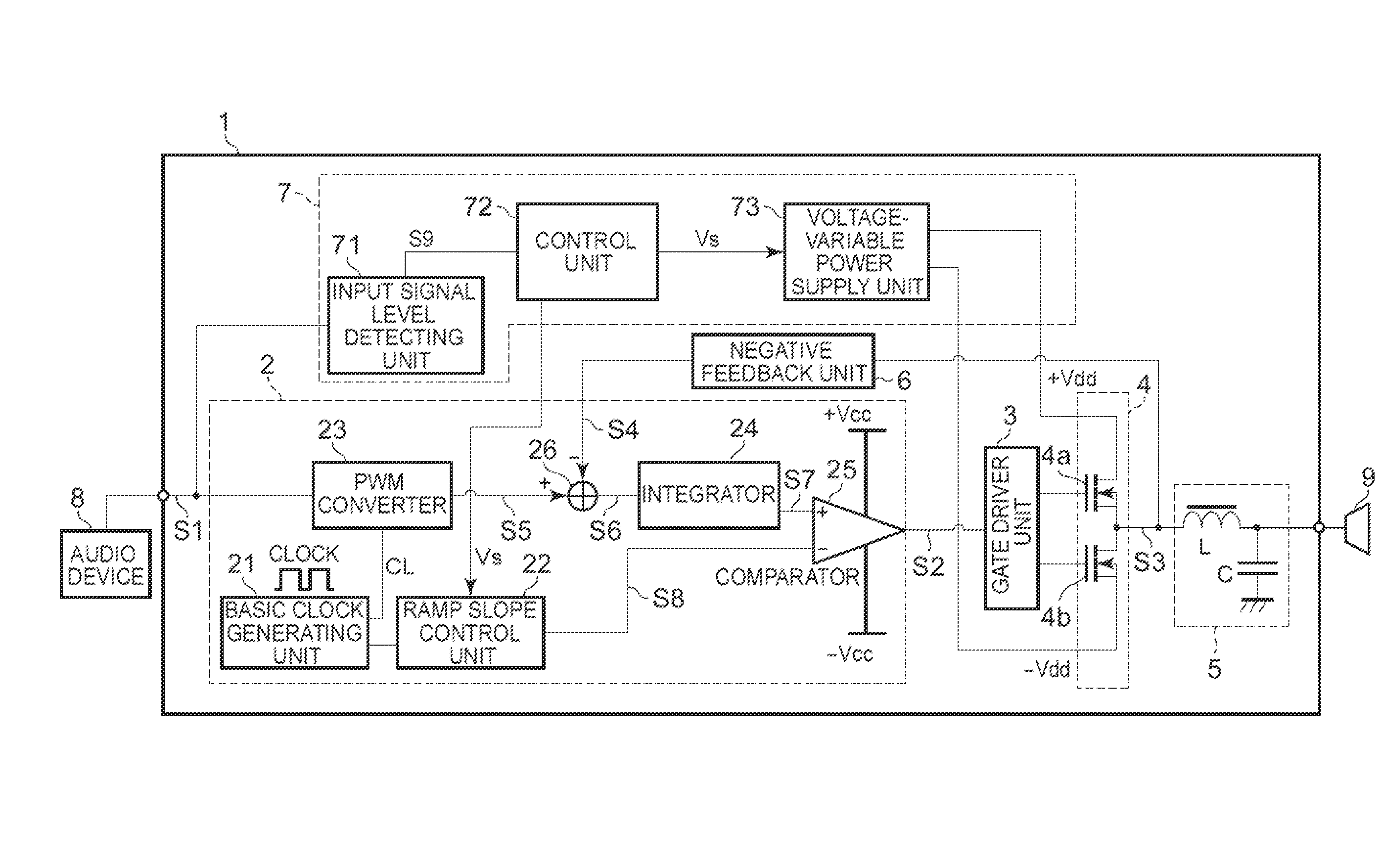
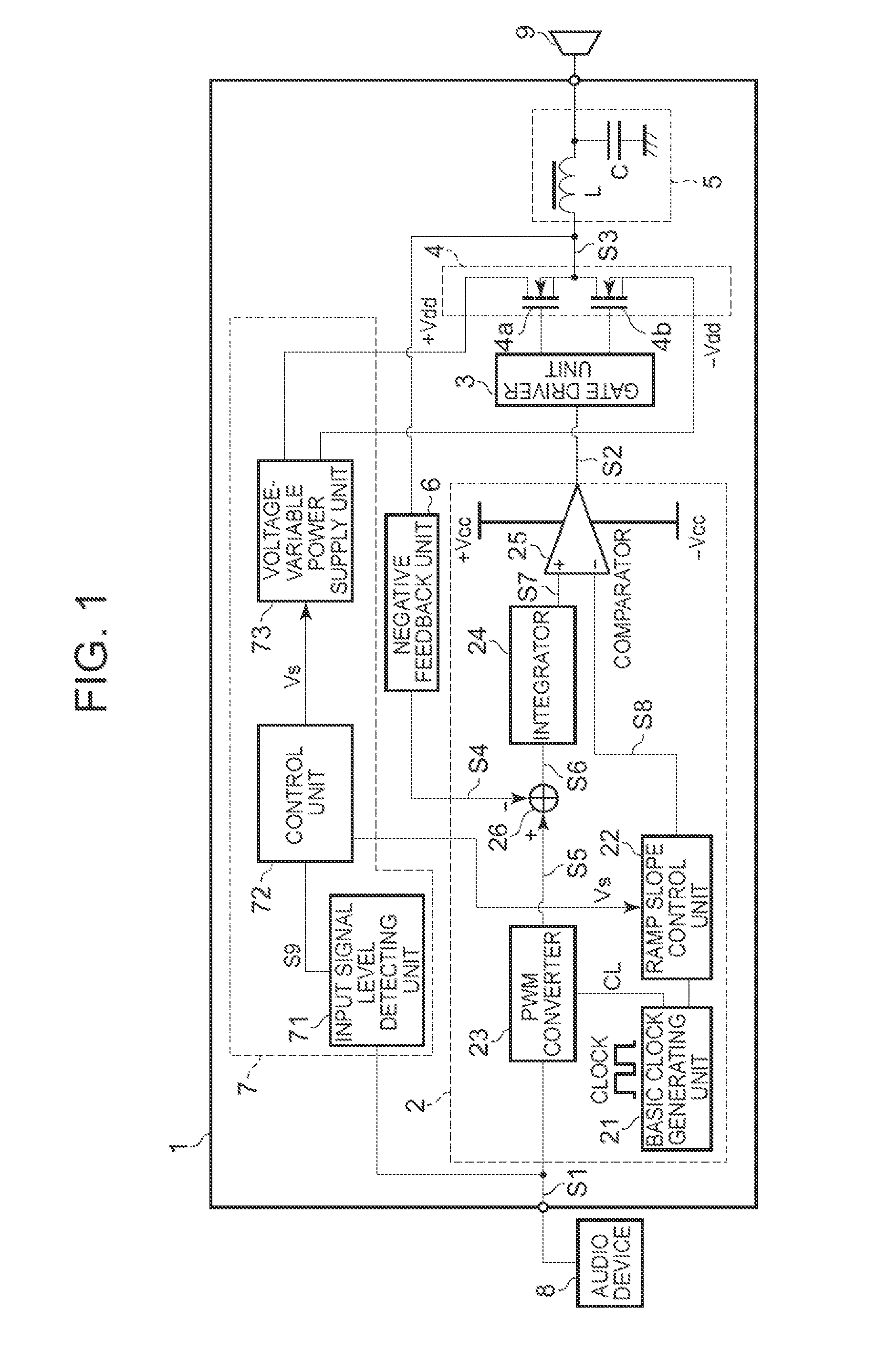
[0019]An amplifier apparatus 1 according to Embodiment 1 of the present invention will now be described with reference to a block diagram of FIG. 1.

[0020]In FIG. 1, the amplifier apparatus 1 in this Embodiment 1 is connected to an audio device 8 from which audio signals are output at line level.

[0021]An audio signal output from the audio device 8 is input into the amplifier apparatus 1 as an input audio signal S1 of the amplifier apparatus 1, subjected to power amplification in the amplifier apparatus 1, and output to a speaker 9. The speaker 9 converts, to sound, the audio signal output from the amplifier apparatus 1 after being subjected to power amplification, and emits the sound.

[0022]Further, the amplifier apparatus 1 and the audio device 8 are connected to a DC power supply (not shown) for supplying power required to activate them. Note that the power supply required to activate each apparatus / device is not limited to the DC power supply, and an AC power supply may also be use...

embodiment 2

[0110]An amplifier apparatus 1a according to Embodiment 2 of the present invention will be described below with reference to a block diagram of FIG. 4. Note that the following will describe only a point different from the amplifier apparatus 1 of FIG. 1 shown in Embodiment 1 of the present invention and description of the same structural portions will be omitted.

[0111]The amplifier apparatus 1a differs from the amplifier apparatus 1 in Embodiment 1 in that a detector 10 is included.

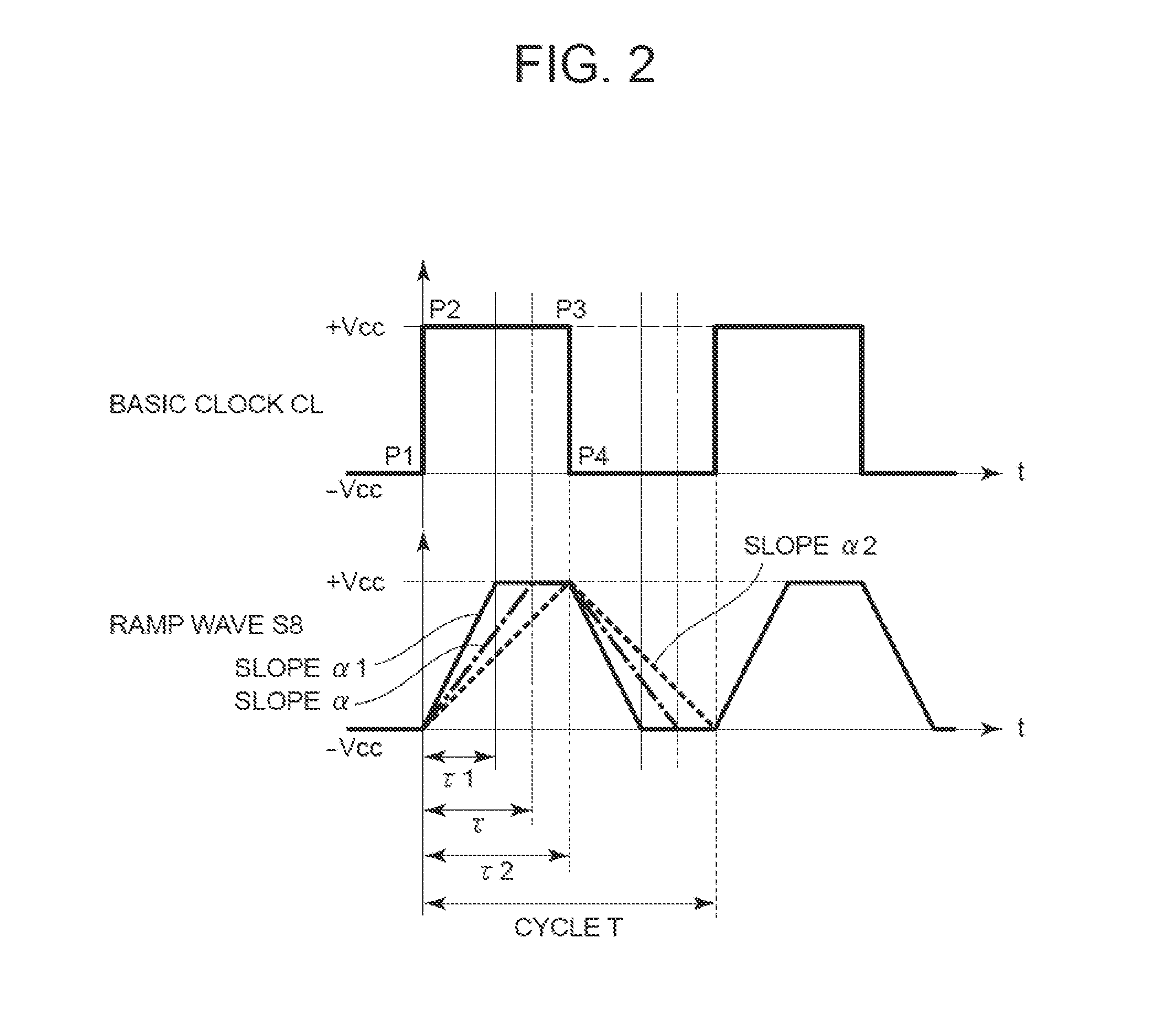
[0112]The detector 10 detects a power-supply voltage value +Vdd supplied to a power amplification unit stage 4, attenuates the detected voltage value +Vt at a predetermined ratio in a resistor dividing system, and outputs it to a ramp slope control unit 22a as information Vdet for controlling the slope α of the ramp wave S8.

[0113]This is to produce a similar effect to the amplifier apparatus 1 in which the control unit 72 outputs target set voltage value information Vs to the ramp slope control unit 22 as...

embodiment 3

[0132]An amplifier apparatus 1b according to Embodiment 3 of the present invention will be described with reference to a block diagram of FIG. 6. In FIG. 6, the amplifier apparatus 1b of Embodiment 3 is connected to an audio device 8 from which digital audio signals are output at line level. An audio signal output from the audio device 8 is input into the amplifier apparatus 1b as an input audio signal S1 of the amplifier apparatus 1b, subjected to power amplification in the amplifier apparatus 1b, and output to a speaker 9. The speaker 9 converts, to sound, the audio signal output from the amplifier apparatus after being subjected to power amplification, and emits the sound.

[0133]Further, the amplifier apparatus 1b and the audio device 8 are connected to a DC power supply (not shown) for supplying power required to activate them. Note that the power supply required to activate each apparatus / device is not limited to the DC power supply, and an AC power supply may also be used arbit...


PUM


Abstract

Disclosed is a technique for reducing noise superimposed on an output signal while keeping loop gain constant without increasing the circuit scale and without changing the transfer function of the amplifier apparatus (frequency characteristics of gain and phase). According to the technique, there are included a power-supply voltage control unit 7 for detecting the amplitude level S9 of an input audio signal S1 and outputting power with a voltage value indicated by target set voltage value information Vs corresponding to this amplitude level S9, and a PWM modulation unit 2 including a PWM converter 23 for converting the pulse width of the input audio signal S1 and a correction unit for correcting the signal modulated by the PWM converter 23. The PWM modulation unit 2 corrects the pulse width of a PWM signal S5 modulated by the PWM converter 23 so that the correction unit will cancel out a change in amplification gain of a power amplification unit 4 according to the target set voltage value information Vs.

Description

TECHNICAL FIELD[0001]The present invention relates to an amplifier apparatus for amplifying the power of an input signal, and particularly to an amplifier apparatus for controlling the voltage of a power supply at a power amplifier stage to improve the S / N ratio of an output signal and power efficiency at the power amplifier stage.BACKGROUND ART[0002]Conventionally, there has been a technique for using a voltage-variable power supply as the power supply of an amplifier apparatus to make it follow the level of an input audio signal to the amplifier apparatus in order to increase or decrease the value of power supply voltage to be supplied to a power amplifier stage, thereby reducing noise superimposed on an output signal and improving the power efficiency at the power amplifier stage. In this case, the power supply voltage to be supplied to the power amplifier stage is made to follow the level of the input audio signal. Therefore, when the level of the input audio signal is low, sinc...

Claims


Application Information

Patent Timeline
Patent Type & Authority Patents(United States)
IPC IPC(8): H03F99/00H03F3/38H03F3/20H03F3/217
CPCH03F3/20H03F3/2173H03F1/0233H03F1/26H03F3/183H03F3/217H03F2200/03H03F2200/351
Inventor ZHANG, MINGXUEOZAKI, SEIGOHAGA, TSUYOSHI
Owner PANASONIC INTELLECTUAL PROPERTY MANAGEMENT CO LTD
Why Eureka
Try Eureka