Landing gear door system and operation method

a technology of landing gear and gear door, which is applied in the field of landing gear door system, can solve the problem that the landing gear cannot be deployed from the landing gear bay, and achieve the effect of reducing the size of the actuator

Active Publication Date: 2021-12-30
AIRBUS OPERATIONS SL
View PDF2 Cites 0 Cited by
  • Summary
  • Abstract
  • Description
  • Claims
  • Application Information

AI Technical Summary

Benefits of technology

[0028]As a result, the additional actuator may be a smaller actuator. Thus, the optimization of the structure and the reduction of the actuator size are advantages achieved by the claimed invention.

Problems solved by technology

In the closed position of the landing gear doors, the landing gear cannot be deployed from the landing gear bay, as the landing gear door covers the opening to impede its deployment.
As previously stated, the increase of the applied load causes peak loads that may cause problems.
4. The up-lock is latched when the door reaches the pre-crushed condition.
5. The actuator is depressurized.

Method used


Image

  • Landing gear door system and operation method
  • Landing gear door system and operation method
  • Landing gear door system and operation method

Examples


Embodiment Construction

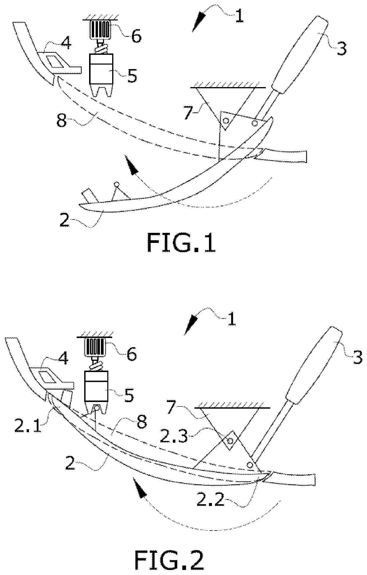
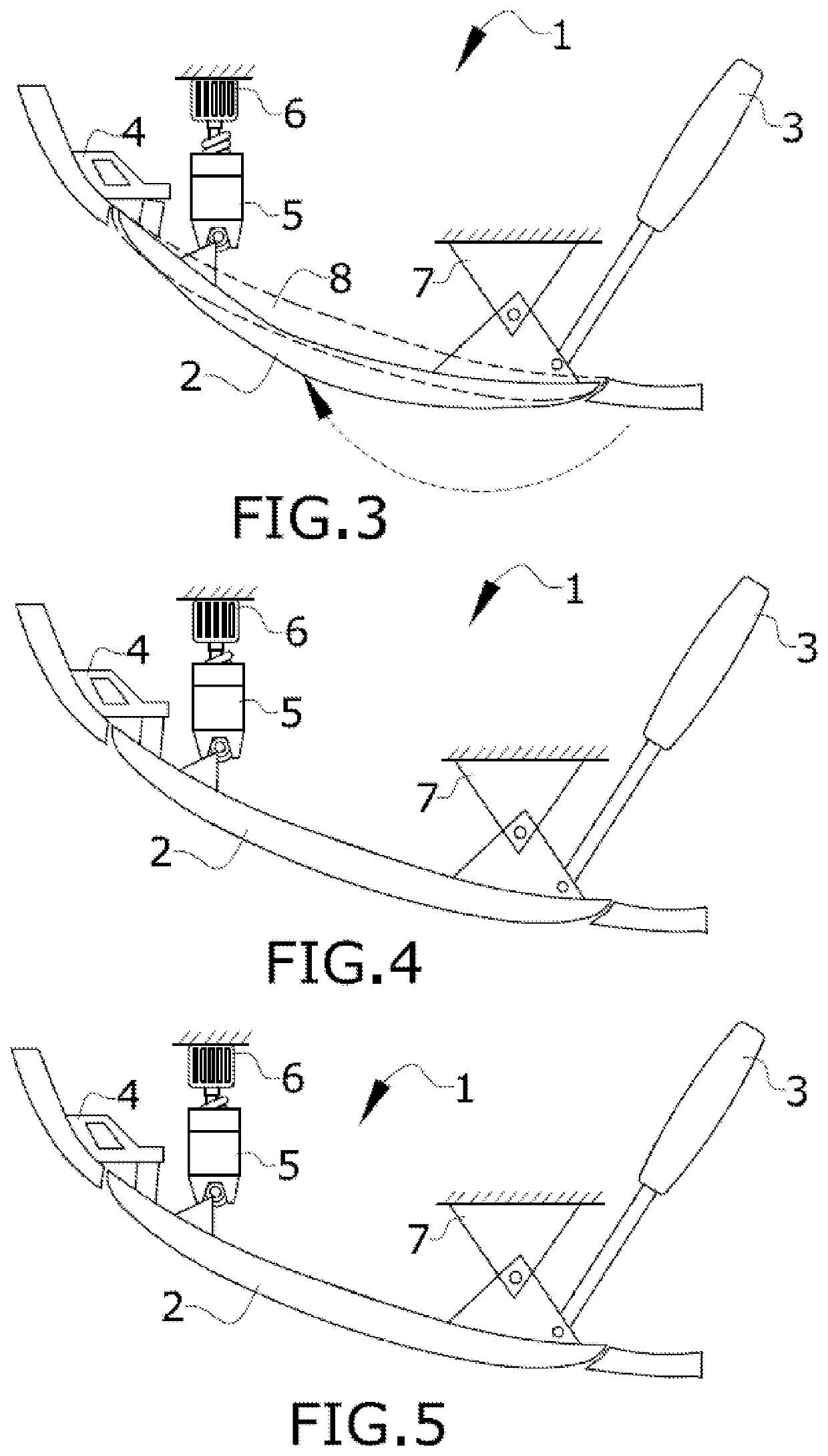
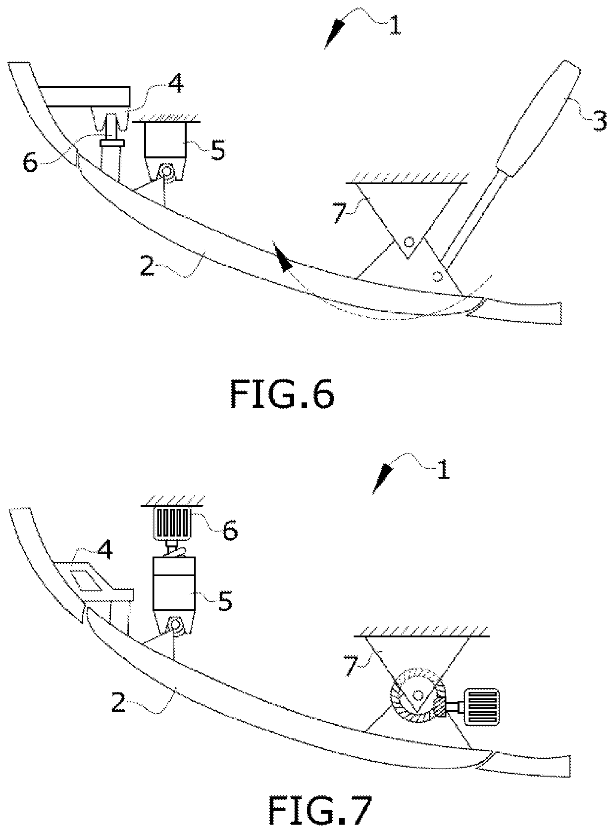
[0037]FIGS. 1 to 7 disclose a landing gear door system comprising:

[0038]A landing gear bay (1) for accommodating the landing gear in a retracted position (not represented).

[0039]A landing gear door (2) that closes the landing gear bay opening (8) comprising a distal end (2.1), a proximal end (2.2) and a hinge line (2.3) located between the distal end (2.1) and the proximal end (2.2). The proximal end (2.2) is located in the proximity of the hinge line (2.3) of the landing gear door (2) and the distal end (2.1) is the opposite end of the door (2).

[0040]An actuator (3) attached to the landing gear bay (1) and connected to the landing gear door (2) for operating the landing gear door (2) between the open and the closed position. The actuator (6) may be hydraulically or pneumatically actuated. In the shown embodiments, the actuator (3) is being connected to the landing gear door (2) in the proximity of the proximal end (2.2).

[0041]A lock (5) located in the landing gear bay (1) and confi...


PUM


Abstract

A landing gear door system, including a landing gear bay including an opening and accommodating a landing gear in a retracted position, a landing gear door for opening and closing the opening, an actuator for operating the landing gear door between an open and a closed position, a lock located in the landing gear bay and latching the landing gear door in the closed position, a stop fitting located in the landing gear bay and configured to be in connection with the landing gear door at least in its latched position. The landing gear door system further includes an additional actuator configured to apply a force to the landing gear door in its closed position and to elastically deform the landing gear door towards the landing gear door bay.

Description

CROSS-REFERENCES TO RELATED APPLICATIONS[0001]This application claims the benefit of the European patent application No. 20382557.5 filed on Jun. 24, 2020, the entire disclosures of which are incorporated herein by way of reference.FIELD OF THE INVENTION[0002]The present invention relates to a landing gear door system and its operation method. The landing gear door system and operation method of this invention help to mitigate peak loads produced at the landing gear door.BACKGROUND OF THE INVENTION[0003]During flights, landing gears are retracted in landing gear bays which are closed by landing gear doors. The doors are hydraulically operated by an actuator. The doors are closed after extension / retraction of the gears and are pulled into contact with stops mounted on the belly fairing.[0004]In the closed position of the landing gear doors, the landing gear cannot be deployed from the landing gear bay, as the landing gear door covers the opening to impede its deployment. In the open ...

Claims


Application Information

Patent Timeline
Patent Type & Authority Applications(United States)
IPC IPC(8): B64C25/16B64C25/26B64C25/24
CPCB64C25/16B64C25/24B64C25/26B64C1/1407
Inventor LÓPEZ LÓPEZ, LADISLAO
Owner AIRBUS OPERATIONS SL
Why Eureka
Try Eureka