
Inline disconnect for multiphase electric utility line applications

a multi-phase electric utility and inline disconnect technology, applied in the direction of air-break switches, high-tension/heavy-dress switches, switch power arrangements, etc., can solve the problems of increasing installation time and expense, complicated arrangement, etc., and achieve the effect of eliminating mechanical linkages

Active Publication Date: 2021-12-30
SOUTHERN ELECTRICAL EQUIP
View PDF7 Cites 0 Cited by
  • Summary
  • Abstract
  • Description
  • Claims
  • Application Information

AI Technical Summary

Benefits of technology

The present invention is about an improved switch system for multi-phase electrical utility applications. The system includes an inline disconnect component for multi-phase electrical utility applications. The invention includes a load break vacuum bottle interrupter that can control electrical flow through a switch. The load break vacuum interrupter can be placed in series or parallel with other switches to provide selective opening and closing of electrical transmission lines. The system also includes a control box for controlling and providing status information about the switches. The inline switches can be mechanically and electrically isolated from the control box. The invention provides an improved arrangement for group-operated switches for electrical transmission lines. The system can be powered by line power, batteries, or a capacitive source. The invention allows for the elimination of mechanical linkage between switches and provides a more efficient and reliable solution for controlling electrical flow in multi-phase electrical utility applications.

Problems solved by technology

This arrangement is enormously complicated for several reasons.
This can present additional engineering challenges in real-world conditions, particularly at the installation stage; Load Break devices such as vacuum interrupters and their associated operating linkages are mounted outside of the switch path causing electrical clearance issues; site-specific application engineering is generally required, thus increasing installation time and expense.

Method used


Image

  • Inline disconnect for multiphase electric utility line applications
  • Inline disconnect for multiphase electric utility line applications
  • Inline disconnect for multiphase electric utility line applications

Examples


Embodiment Construction

[0031]The present invention includes systems, arrangements, and methods for providing an improved switching system for an electrical transmission lines.

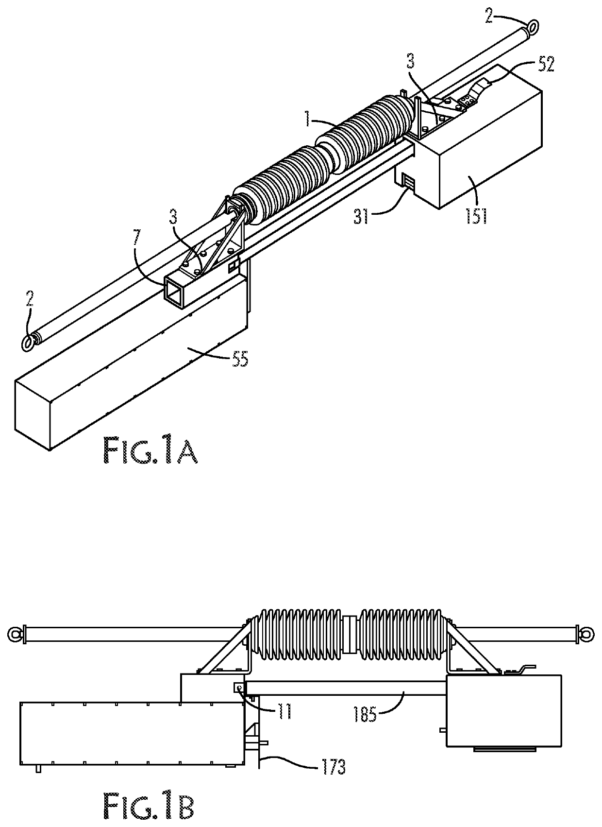
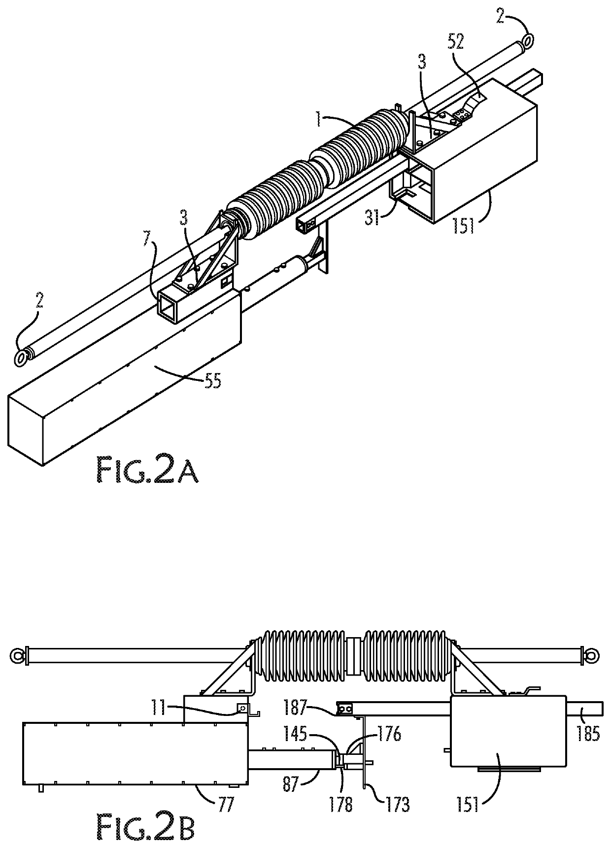
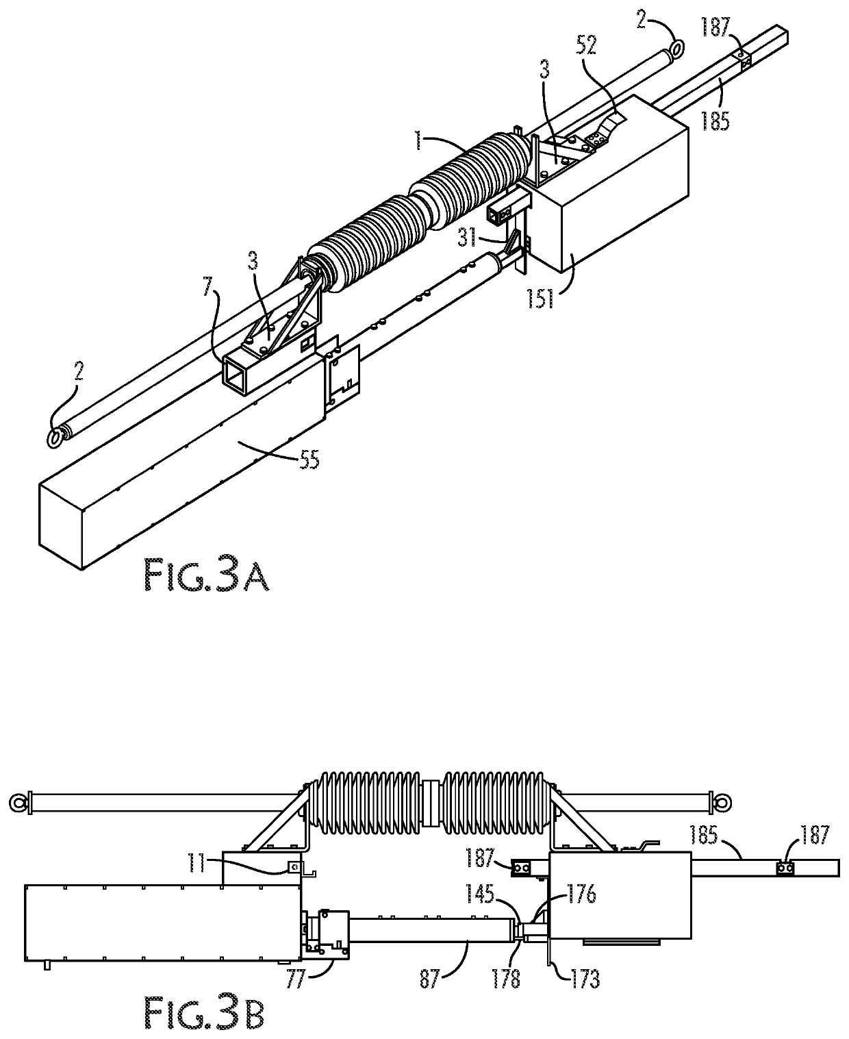
[0032]Referring now to the drawings, FIGS. 1A-5B illustrate one embodiment of the present system, which includes the sequence of operation of a disconnect blade 185 and an interrupter 87. During operational cycles from the closed state to the open state and the reverse cycle of the open state to the closed state all mechanical linkages stay in the same clearance envelope while traveling inline with the original orientation. This movement is critical in keeping balanced line loads as well as clearance gaps between circuit legs during operational cycles. FIG. 6 illustrates the general arrangement of a device according to the present invention. An electric utility pole 205 carries electrical lines 250-252 each associated with one of three phases I, II, III of AC electric power. Each line is attached to the pole and insulated from ground...


PUM


Abstract

A group-operated switching system for multi-phase electrical transmission lines including a number of inline axial switches for opening and closing circuits to control electrical flow through the transmission lines. The switches include axially mounted load break vacuum interrupters and are mechanically and electrically isolated from each other and from a control box. The control box communicates with the inline switches via RF communications. Power for the switch electronics and operations can be provided from line power, a battery, or a capacitive source.

Description

CROSS REFERENCE TO RELATED APPLICATIONS[0001]This application claims priority to and benefit of U.S. Provisional Patent Application No. 63 / 046,250, filed on Jun. 30, 2020, the entirety of which is incorporated by reference herein.FIELD OF THE INVENTION[0002]The present invention relates generally to group-operated switches for electric utility line applications, and more particularly to an inline disconnect for group-operated multi-phase switches that are not mechanically or electrically linked and incorporate interrupting and sensing devices that operate in an axial direction with the switches.BACKGROUND OF THE INVENTION[0003]Conventional electric utility lines are generally arranged wherein alternating currents of differing phases are carried on separate lines from point to point, each supported on the same pole. Each line carries a phase of AC that is offset, for example by 120° in a three-phase arrangement, from the others. These lines are arranged one over the other on the util...

Claims


Application Information

Patent Timeline
Patent Type & Authority Applications(United States)
IPC IPC(8): H01H33/666H01H33/668H01H33/28
CPCH01H33/6661H01H33/28H01H33/668H01H33/36H01H9/167H01H31/32H01H33/022H01H1/66H01H3/26H01H33/666
Inventor PANTO, ANDREW S.THOMAS, BARRY CRAIGLANTER, DOUGSURFACE, DILLON
Owner SOUTHERN ELECTRICAL EQUIP
Learn More